1
\$\begingroup\$

I am new to electronics so I apologize in advance for incorrect terminology.

I have an existing circuit which can be powered with either 13.4v or 14.4v. What I would like to do is treat that voltage difference as a binary switch, where the 13.4v power is OFF and the 14.4v power is ON.

So basically I want to build a circuit that can have an input voltage of 13.4v or 14.4v which would equate to an output of 0v or 14.4v respectively.

I have found and looked into MOSFET transistors as they seem to be the most reasonable way to achieve this but I can't find one that has a gate-source threshold voltage high enough. As in, I can find a 14v Vgs MOSFET but the Vgsth is always too low, usually 6,7 volts. I need the OFF output voltage to be 0v. This is leading me to think this might not be the correct approach.

EDIT: I also want to include that the maximum current draw on the circuit could reach 8 amps but on average should be closer to .5/1 amps.

Can I achieve the circuit I described above with just one MOSFET? Or is what I'm even trying to do reasonable/possible?

Thanks for your time.

\$\endgroup\$
3
  • 3
    \$\begingroup\$ You should be looking at comparators, not discrete devices. \$\endgroup\$
    – The Photon
    Commented Dec 18, 2016 at 22:26
  • \$\begingroup\$ Voltage supervisors might be of use. I'm a bit rusty on this so won't submit an answer. You might need to divide the input voltage down to use a component with a more common voltage threshold, then use the supervisor to drive a FET. \$\endgroup\$ Commented Dec 18, 2016 at 22:44
  • \$\begingroup\$ @LOP_Luke FWIW before you think of a how to do it, make a spec. This lists all inputs , functions and outputs with tolerances and environmental contraints. Like all logic this is how they are defined. with Voh, Vol min max. limits. > then think about reverse polarity and over voltage if needed ( as all automotive designs must) this seems to be hard to do but essential. Then questions are clearer and solutions become more obvious with fewer feedback questions. Separate nice to have from Must Haves. Like an indicator... or cost sensitive. or ... hysteresis.. or input noise.. surge current... \$\endgroup\$
    – D.A.S.
    Commented Dec 21, 2016 at 1:21

3 Answers 3

4
\$\begingroup\$

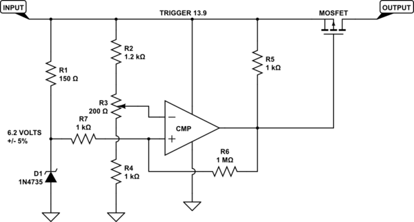
ThePhoton has it right in comments. You need a comparator to make this sort of comparison reliably. What you want is something like

schematic

simulate this circuit – Schematic created using CircuitLab

This will give you zero output until the input gets above (nominally) 13.9 volts, which is halfway between 13.4 and 14.4. Since parts have tolerances, particularly the zener diode on the left, the 200 ohm pot can be used to adjust for component variation. The 1Mohm/1kohm combination is not necessarily important, particularly if your inputs really are the two values you've described. However, they are a good idea, and provide about 15 mV of snap action (hysteresis) if the input just happens to be near the trigger voltage. There are lots of comparators available, although you'll have to make sure you get one which can handle 15 volt supplies (not all can nowadays), and if you want to go with an oldie but goodie you can get an LM311 or LF311. Or you can use 1/4 of an LM339. Both are pretty cheap.

This works as follows: For any input above about 6.2 volts, the + input will be around 6.2 volts. The input is divided by about a factor of 2.2 (depends on the pot setting) and for voltages less than 13.9 volts the - input will be less than the + input, so the comparator output will be high. This will keep the MOSFET turned off. Note that that'a a p-type, and almost anything will work in this application. Also note, though, the MOSFETs do have some leakage current, typically in the area of 1 mA or a bit less, so the MOSFET will not be "completely" off. If you're driving a high-impedance load you'll need to be careful of this. When the input gets above 13.9 volts or so (again, this will depend on the pot setting) the - input will become higher than the + input, the comparator output will go low, and the MOSFET will turn on.

EDIT - Also note that 200 ohms for R3 will work well as long as you use 1% resistors, which are dirt cheap these days. If you elect to go even cheaper and use 5% or (God help us) 10% units, you will probably have to use a larger pot - 500 ohms ought to work.

\$\endgroup\$
4
  • \$\begingroup\$ "halfway between 12.4 and 13.4?" You mean 13.4 and 14.4? \$\endgroup\$ Commented Dec 19, 2016 at 0:02
  • \$\begingroup\$ Drat. Pesky slave labor fingers. \$\endgroup\$ Commented Dec 19, 2016 at 1:41
  • \$\begingroup\$ @WhatRoughBeast thank you for the very detailed answer. I just have a few questions: How are you calculating that 6.2 cutoff voltage? Is that based off the values of the resistors? POT stands for potentiometer right? Is that just for testing? I assume I would only have 1 value there in the final circuit. The voltage of the comparator at HIGH is equal to Vcc I assume so does that mean I still need a MOSFET with a Vgs below 13.9? I also meant to mention in the question that I have a relatively high peak current which could reach up to 8 amps, does that change the circuit? Thank you for the help! \$\endgroup\$
    – LOP_Luke
    Commented Dec 19, 2016 at 19:44
  • 1
    \$\begingroup\$ 6.2 is the zener voltage. For inputs less than that voltage it is essentially an open circuit, then clamps at the voltage for larger inputs. Subject to 5% unit-to-unit variation. 150 ohms gives about the right current for nominal operation - look up the data sheet. Yes, POT is a potentiometer. You would need to build it into the circuit and make a final adjustment to compensate for various component tolerances. At HIGH you don't want the MOSFET on. Above 13.9 the comparator out is low, so there is about 13-14 volts from gate to source. Use a MOSFET rated for the current, but it doesn't change. \$\endgroup\$ Commented Dec 19, 2016 at 20:58
1
\$\begingroup\$

You probably can't do this effectively with a single MOSFET.

For one thing because the turn-on does not happen very abruptly. It could require a variation of several volts on the gate between when the FET starts to allow a little current through to where it is fully "on".

Second, because the threshold voltage varies from device to device and when the device's temperature changes.

You'll get a much cleaner solution if you investigate comparators, which is a type of product designed to do just about exactly what you're trying to do.

\$\endgroup\$
1
  • \$\begingroup\$ That said it's also possible to build a comparator with discrete components such as MOSFETS. Not quite reliable if temperature varies much though. On the other hand it would be a good case study for a novice. \$\endgroup\$
    – user59864
    Commented Dec 18, 2016 at 22:43
1
\$\begingroup\$

Consider a TL431 voltage reference. You can use this as a comparator, and it includes a temperature-compensated voltage reference, so all you'd need is a two-resistor voltage divider to convert the input voltage (13.9V) to the reference voltage (2.495V). And then a MOSFET on the output to get the 14.5 V output you want.

\$\endgroup\$
1
  • \$\begingroup\$ +1 TL431 is indeed a perfect fit for these situations. An example schematic tailored for the specific OP requirements would have been worth it, however. \$\endgroup\$
    – dim
    Commented Dec 19, 2016 at 21:23

Your Answer

By clicking “Post Your Answer”, you agree to our terms of service and acknowledge you have read our privacy policy.

Not the answer you're looking for? Browse other questions tagged or ask your own question.