3
\$\begingroup\$

I've stumbled onto something that I don't understand.

I've wired up a phase shift oscillator using a BC337 transistor (datasheet here). According to the datasheet, \$V_{BE(on)}=1.2\ V\$ However, using my multimeter (and after doing the theoretical calculations), I have found that my \$V_{BE}\$ is about 0.6V, which should apparently force the transistor into cutoff.

Here is my circuit:
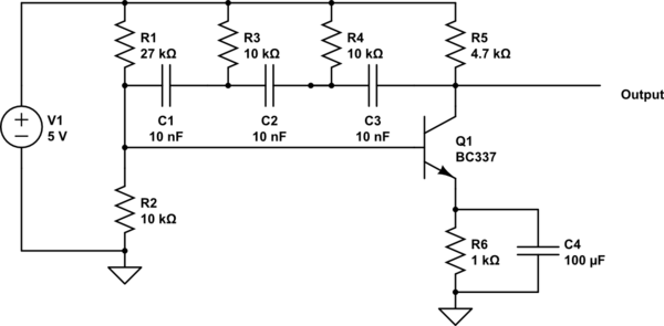
schematic

simulate this circuit – Schematic created using CircuitLab

The oscillator is functioning, producing a slightly distorted sine wave of about 1.5 V peak-to-peak and at about 560 Hz. I measured \$I_E\$ to be around 7 mA, but couldn't measure \$I_B\$ without my multimeter ruining the output of the circuit.

As far as I know, this output should indicate that the transistor is in active mode, but if \$V_{BE}\$ is that small, shouldn't it be in cutoff?

\$\endgroup\$
5
  • 1
    \$\begingroup\$ The value shown as 1.2VDC in the datasheet is the "maximum" value of Vbe. As you might know, typical silicon transistors have about 0.6-0.7VDC, so your Vbe measurement is correct. But for Ie, if you measure 7mA then the voltage across R6 should be 7V, but the supply voltage is 5V. How can it be? If you make DC analysis then you can easily see that quiescent collector (or emitter) current is about (1.25-0.6)/1k=0.65mA. But since this is an oscillator, you might not able to measure DC currents. \$\endgroup\$ Commented Dec 20, 2016 at 4:20
  • \$\begingroup\$ OK, guess I didn't know how to interpret that. In that case everything is fine. Thanks! \$\endgroup\$
    – Mahkoe
    Commented Dec 20, 2016 at 4:29
  • \$\begingroup\$ @Mahkoe Do you want an undistorted sine out? you never asked. \$\endgroup\$
    – D.A.S.
    Commented Dec 22, 2016 at 0:42
  • \$\begingroup\$ @TonyStewart.EEsince'75 Haha thanks for asking. However, I figured that one out on my own. I reduced the gain of the amplifier (by putting the bypass capacitor on the slider of a potentiometer), and that almost completely removed any distortion. \$\endgroup\$
    – Mahkoe
    Commented Dec 23, 2016 at 15:55
  • \$\begingroup\$ Yes it has a narrow hFE gain window for linearity. There are many other ways to do it as well. You ought to be able to get >4Vpp keeping away from Vce(sat) and Vce(max (Imin>10%) \$\endgroup\$
    – D.A.S.
    Commented Dec 23, 2016 at 17:20

1 Answer 1

6
\$\begingroup\$

The value in the datasheet is a maximum value, so any value lower than 1.2 V is within the specified limits.

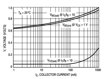
Furthermore, it is specified with 300 mA collector current, where your circuit is requires only about 1 mA collector current, so it's not suprising that you measure Vbe well below the 1.2 V value.

In fact, there's a typical curve provided:

enter image description here

That shows that around 0.6 V is expected when the collector current is this low.

\$\endgroup\$

Your Answer

By clicking “Post Your Answer”, you agree to our terms of service and acknowledge you have read our privacy policy.

Not the answer you're looking for? Browse other questions tagged or ask your own question.