1
\$\begingroup\$

I have this rotary encoder and I am not quite sure how to debounce the internal push button switch (shown in the SW02 diagram).

Any help would be appreciated, I'm a noob with this stuff.

EDIT I would like to implement a hardware debounce

My primary problem is that I need to have my VCC on pin 5 and my ground on pin 3 in order to have my LEDs also work. And I don't know how to make the debounce work properly with that setup.

\$\endgroup\$
6
  • 1
    \$\begingroup\$ hackaday.com/2010/11/09/debounce-code-one-post-to-rule-them-all \$\endgroup\$
    – tyblu
    Commented Mar 6, 2012 at 1:39
  • \$\begingroup\$ oh I wanted to implement a hardware debounce \$\endgroup\$
    – Dan
    Commented Mar 6, 2012 at 1:44
  • 2
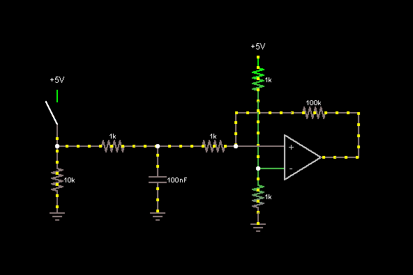
    \$\begingroup\$ @Dan - RC filter the switch output, and feed it through a schmitt trigger device. \$\endgroup\$ Commented Mar 6, 2012 at 1:57
  • \$\begingroup\$ @Dan Why hardware debounce specifically? Where is this button inside the encoder connected to? What is the button used for? In my past experience, only buttons connected to interrupts, counters, reset lines (may be, this is not the complete list) needed debouncing. \$\endgroup\$ Commented Mar 6, 2012 at 6:41
  • 1
    \$\begingroup\$ @NickAlexeev: That reminds me: one of the design changes from the Commodore 64 to the Commodore 128 was that the former had a debounce circuit between the "Restore" key and the processor's NMI, while the latter did not. Some programs which didn't like getting two NMI's in quick succession had trouble on the C128 when RESTORE was pressed. \$\endgroup\$
    – supercat
    Commented Mar 6, 2012 at 15:44

3 Answers 3

2
\$\begingroup\$

enter image description here

Note: You can replace the op-amp assembly with a schmitt-trigger inverter or buffer, to make your life easier. Anything with some input hysteresis will work.

\$\endgroup\$
0
1
\$\begingroup\$

To effectively debounce an input, one must decide how the debounced logic should interpret various signals (e.g. what must the input signal do to be regarded as a "high", and what must it then do to be considered a "low"). In many cases, if precise timing isn't required, the simplest way to debounce a push button is to simply sample it periodically. If the sampling interval exceeds the longest bounce time, but the duration of every push, minus its bounce time, exceeds the sampling interval, then every button push will register exactly once.

If more precise input timing is needed, another useful approach is to have an input transition trigger a timing circuit, and ignore the state of the input until the timer expires (one may if desired ignore the input for different lengths of time following a press and release). This may in many cases be done fairly conveniently in software, even if the input is wired to an interrupt pin (the pin's interrupt service routine disables the pin's interrupt, but sets up a timer whose interrupt service routine will re-enable the pin's interrupt).

Another hardware approach if one has both normally-open and normally-closed contacts available, is shown here. There are quite a few variations, based upon whether one wishes to run +5 and ground out to the switches and have one return wire, or whether one would rather run ground only and have two return wires, or use switch-mounted diodes and have two wires total. These approaches can be especially advantageous when interfacing to low-power circuitry switches that may stay for a long time in each state, since current only has to flow through the switch when it changes state. Further, they are essentially immune to even the most horrible switch-bounce conditions imaginable (it's theoretically possible that just the 'right' pattern of switch bounce could trigger metastability, but the probability of that happening is extremely low). The only disadvantage is the requirement that the switch have both normally-open and normally-closed contacts.

\$\endgroup\$
1
\$\begingroup\$

There are also specialized switch debouncing ICs, which have a hardware counter to determine the debouncing delay. Maxim MAX6816 and Atmel U6032B, for example.

enter image description here

The image comes from application note 287, which has more details.

\$\endgroup\$

Your Answer

By clicking “Post Your Answer”, you agree to our terms of service and acknowledge you have read our privacy policy.

Not the answer you're looking for? Browse other questions tagged or ask your own question.