0
\$\begingroup\$

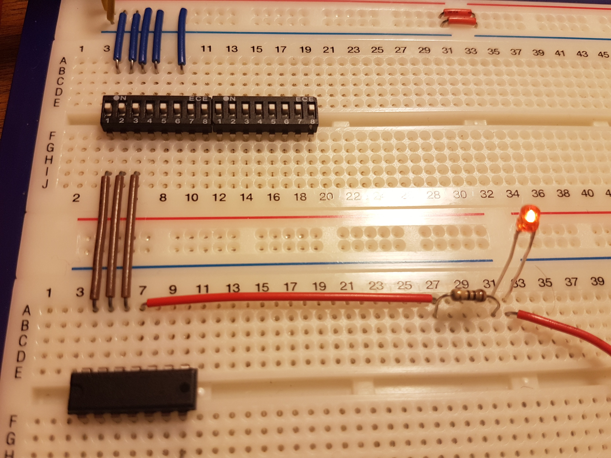
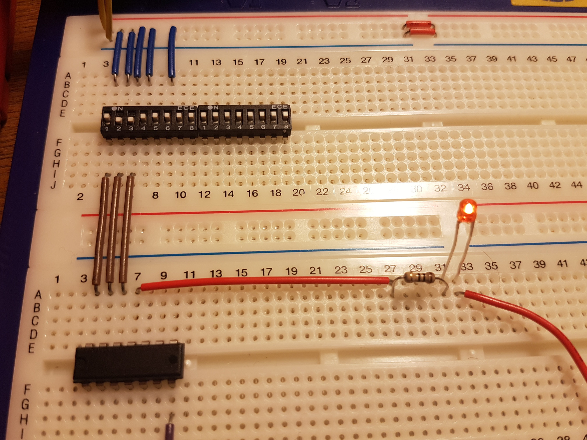
I'm trying to get started making logic circuits but I'm not making much progress even with the most basic. I have a SN7408 which is an AND gate however it doesn't matter what I put over the inputs (1A and 1B) I get continuity from Vcc to 1Y which is rather irksome.

I have been playing around with a few USB power sources 5v from a 230v mains adapter. 5v from my macbook and 5v from a recently purchased phone powerbank.

I'm guessing I'm burning out the chips. How can I stop doing that?

Any help gratefully appreciated!

Cheers,

Andrew -

enter image description here enter image description here

\$\endgroup\$
9
  • \$\begingroup\$ Could it be that you have just fried your part while "playing around"? \$\endgroup\$
    – Eugene Sh.
    Commented Dec 23, 2016 at 20:44
  • \$\begingroup\$ I am frying a LOT of parts :( \$\endgroup\$ Commented Dec 23, 2016 at 20:46
  • \$\begingroup\$ Are you supplying +5 to pin 14? Assuming that the dark wire seen at the very bottom of your pictures is hooked up to pin 7 and tied to ground, then it looks like pin 14 is wired to a brown wire and up towards a switch block above (switch #1.) Do you supply +5 V in that fashion? \$\endgroup\$
    – jonk
    Commented Dec 23, 2016 at 20:50
  • 3
    \$\begingroup\$ Where are your pulldowns? \$\endgroup\$ Commented Dec 23, 2016 at 20:54
  • 1
    \$\begingroup\$ Bypass capacitor close to each IC, 0.1uF directly across the supply, right at the IC pins, is standard practice. Most ICs will not work right if the supply is unstable. \$\endgroup\$
    – MarkU
    Commented Dec 23, 2016 at 21:08

2 Answers 2

3
\$\begingroup\$

To expand on Peter's explanation, your two inputs are currently either switched to +5V, or open. The problem here is that both +5 and "open" are seen as logic "one", and so the AND gate output will always be a "one". You can fix this by putting strong pulldown resistors (220 Ohm) on the inputs, but with TTL it is much better to use pull-up resistors and switch to ground. The pullups can be 1K to 10K or so. With CMOS logic the resistors can be much larger, but they are still necessary.

\$\endgroup\$
6
\$\begingroup\$

The inputs of bipolar TTL (74nn, 74LSnn) parts will appear as a High when not connected, and will source 1 mA or so (varies with specific family) when taken low, so they are normally used with a switch between the input pin and Ground to ensure that the input will really be recognized as Low when we want it Low. It is generally recommended to also use a 5 - 10K pull-up resistor from the input pin to Vcc, to ensure that the input will be seen as High when the switch is open.

CMOS parts (74HCnn, 74ACnn) have very high input impedances, and the inputs will float randomly if not connected. All inputs (even unused ones) MUST have pull-up or pull down resistors to ensure that they will be in a known state when not driven High or Low by other means.

\$\endgroup\$

Your Answer

By clicking “Post Your Answer”, you agree to our terms of service and acknowledge you have read our privacy policy.

Not the answer you're looking for? Browse other questions tagged or ask your own question.