1
\$\begingroup\$

I am working on putting together an Arduino board that would read signals sent between two modules in a car. The signals are sent as 8V square waves.

An example of a message sent this way would be a sequence that is 12mS long consisting of a 8V high for 6mS then a 0V low for 9mS repeated back to back 14 times.

The problem I have is that if I put more than 5V into a digital pin on an Arduino I will blow the board. This gets worse because with this being in a car it is completely possible that the digital pin might accidentally see full automotive voltage of roughly 15V.

My thought was to use a voltage divider that would bring 15V down to 5V this way even if the digital pin saw the full 15 voltages it wouldn't hurt the Arduino. I would also look at Zener or other method for over-voltage protection.

My concern, though, is the timing is in milliseconds and I don't want the timing to be off or I won't be able to decode messages accurately. What I am really looking for is way to read these signal in real-time just at a lower voltage. Will this work or do I need to go a different direction?

\$\endgroup\$
1
  • \$\begingroup\$ Use a resistor divider or op amp. \$\endgroup\$
    – Voltage Spike
    Commented Dec 24, 2016 at 8:01

2 Answers 2

1
\$\begingroup\$

You really should want some hysteresis as well as signal conditioning to your Arduino input levels. I'll get to that near the end.

I don't know what's powering your Arduino. If you are supplying it through an inexpensive \$5\:\textrm{V}\$ converter that works off the automotive voltage rail, you may find that it protect your Arduino from periodic load dumps.

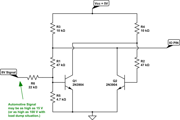
Assuming you have a clean and safe \$5\:\textrm{V}\$ supply for the Ardiuno, then your main worry is if your Arduino I/O pin gets exposed to an external voltage (relative to the ground, of course) that is above the \$5\:\textrm{V}\$ supply rail. In such cases, the protection diodes will kick in and start leaking current into the supply rail. On most processors I've used before, I find that observing a maximum of \$2\:\textrm{mA}\$ meets the absolute maximum specifications. However, you may need to look up your specific processor to get the actual value for it. Since you didn't mention the exact Arduino board, I can't look it up for you. But the following circuit should be entirely safe to use and is easy to make.

schematic

simulate this circuit – Schematic created using CircuitLab

The above circuit uses two very cheap BJTs to create the hysteresis and the desired output signal. The output to the I/O pin is low when your signal is low and is high when the signal rises over about \$3.9\:\textrm{V}\$ (rising direction.) In the falling direction, the signal must go below about \$2\:\textrm{V}\$ for the output to return low. So the circuit includes a hysteresis band that is almost \$2\:\textrm{V}\$ wide, centered over about \$3\:\textrm{V}\$. So, good noise tolerance.

\$R_6\$ (and \$R_5\$) provides plenty of protection, as well. You could add a zener. But I don't think it's needed. In the case of supplying \$15\:\textrm{V}\$ to the signal input, the \$Q_1\$ base will experience about \$400\:\mu\textrm{A}\$ of base current. Which should be just fine. Even with \$100\:\textrm{V}\$ at the signal input \$Q_1\$'s base still sees only \$4\:\textrm{mA}\$. And either way, the I/O pin is protected. (Even if \$Q_1\$ completely fried all pins short for some reason.)

It also should be plenty fast enough for your needs.

\$\endgroup\$
0
\$\begingroup\$

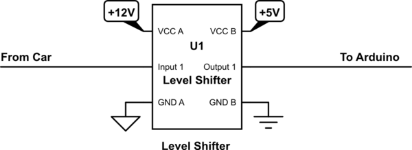
You can use a voltage shifter or voltage translator. You need to provide the battery voltage though. CD4010B-Q1 CMOS Hex Buffer/Converter

Voltage Level Translation Guide

schematic

simulate this circuit – Schematic created using CircuitLab

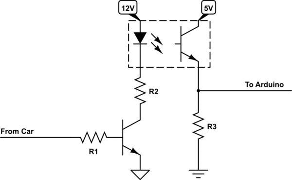
You can also use an optocoupler (May be with or without the driver transistor depending on the available current of your input signal.)

schematic

simulate this circuit

Both of these solutions will give you propagation delays in the vicinity of 100nS using commercial grade components. So you can use them safely in application of a few kilohertz.

\$\endgroup\$

Your Answer

By clicking “Post Your Answer”, you agree to our terms of service and acknowledge you have read our privacy policy.

Not the answer you're looking for? Browse other questions tagged or ask your own question.