3
\$\begingroup\$

I'm trying to simulate a voltage dependent current source in LTSpice and I need to have a limited output current. Here is the directive that I am using:

IOUT = LIMIT( K1 * V(1,0), 0.001, -0.001)

In my schematic, IOUT is a regular current source. In this case the current source has a transconductance equal to K1, and samples the voltage across nodes 1 and 0. (And limits the output current to 1mA.)

The weird thing is that my LTSpice directive works fine without the "V(1,0)"

IOUT = LIMIT( K1, 0.001, -0.001)

So does LTSpice not support the V() function or something? How am I supposed to simulate a voltage dependent current source with a limited output current?

\$\endgroup\$
7
  • \$\begingroup\$ Which element have you placed in the schematic? Bi? Bi2? I? G? F? [Misc]/Gpoly? \$\endgroup\$ Commented Jan 6, 2017 at 7:43
  • \$\begingroup\$ If by V(1,0) you actually mean (V(N001)-V(N002)), you might try that instead. LTSpice tends to use node names that are preceded by "N". \$\endgroup\$
    – jonk
    Commented Jan 6, 2017 at 8:54
  • \$\begingroup\$ @jonk I tried using that syntax but LTSpice is still throwing an error for some reason. For some strange reason I can't get the V() command to work properly on LTSpice in Mac OS X. Has anyone been able to make this command work in OS X? \$\endgroup\$
    – Takide
    Commented Jan 9, 2017 at 19:48
  • \$\begingroup\$ @Takide You can get an example of how to write it by left-clicking on a node (red probe visible) and then, without releasing the left-click, dragging over to another note to see a black probe visible, and releasing. The display will show the proper formula for the difference. \$\endgroup\$
    – jonk
    Commented Jan 9, 2017 at 20:09
  • 1
    \$\begingroup\$ @Takide limit() is a behavioral function (and also can be used in the plot pane.) Just select "bi" from the F2 list and drop it down. Then program in your function as "I=LIMIT(....)" and run. \$\endgroup\$
    – jonk
    Commented Jan 10, 2017 at 6:21

2 Answers 2

4
\$\begingroup\$

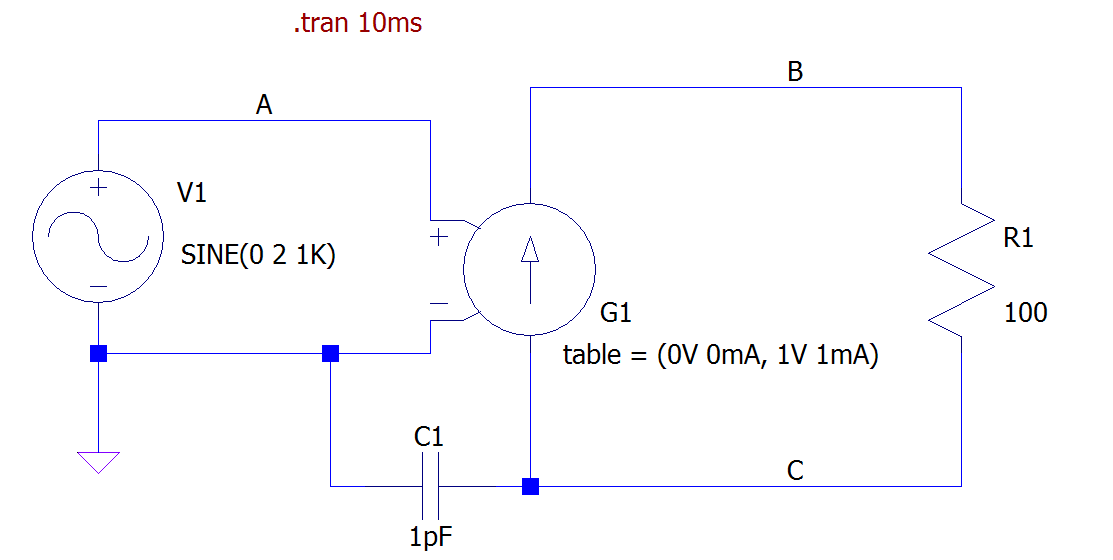
Just use the G circuit element (voltage controlled current source) with a lookup table (LUT) specification:
enter image description here

Note: the capacitor C1 is there only to avoid an error because the simulator doesn't like node C to be floating.

This is the relevant section of the online help (emphasis mine):

G. Voltage Dependent Current Source Symbol Names: G, G2

There are three types of voltage dependent current-source circuit elements.

Syntax: Gxxx n+ n- nc+ nc-

This circuit element asserts an output current between the nodes n+ and n- that depends on the input voltage between nodes nc+ and nc-. This is a linearly dependent source specified solely by a constant gain.

Syntax: Gxxx n+ n- nc+ nc- table=(, , ...)

Here a lookup table is used to specify the transfer function. The table is a list of pairs of numbers. The second value of the pair is the output current when the control voltage is equal to the first value of that pair. The output is linearly interpolated when the control voltage is between specified points. If the control voltage is beyond the range of the look-up table, the output current is extrapolated as a constant current of the last point of the look-up table.

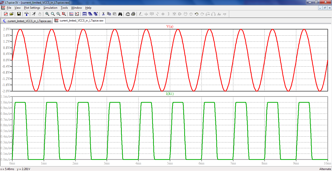
Here are the results of the simulation:
enter image description here

As you can see you only need to specify two points in the LUT if you just want a VCCS with an hard limiting characteristics, i.e. linear inside a given voltage range and fixed saturated limit out of that range.

\$\endgroup\$
5
  • \$\begingroup\$ If LTspice would treat the capacitor as ideal, it wouldn't have any effect in DC, but a default Rpar is added which makes it useful for both DC and AC this way. Or you could simply ground the right side, too. \$\endgroup\$ Commented Jan 7, 2017 at 7:00
  • \$\begingroup\$ @aconcernedcitizen "a default Rpar is added" Maybe I didn't understand exactly what you meant: do you mean that LTspice automatically adds an Rpar value? I don't think this is correct. To my knowledge, if you want to model parasitics for a cap you have to provide explicit values for them. For example, you could specify both an Rser and an Rpar for a cap right clicking on the symbol and adding the relevant parameters. \$\endgroup\$ Commented Jan 7, 2017 at 10:23
  • \$\begingroup\$ @aconcernedcitizen BTW, grounding the right side is a possibility, but it limits the applicability of the model. The OP could want to have the current source not referenced to ground, for example when modeling the behavior of devices like FETs not having their source terminal connected to ground. \$\endgroup\$ Commented Jan 7, 2017 at 10:26
  • \$\begingroup\$ Yes, LTspice adds the default Rpar, behind the curtains, which (IIRC) is equal to 1/Gmin, in the same manner that a default 1mOhm series resistance is added to inductors (as long as they have no coupling and/or they're not behavioural or Chan core). Though, for coupling between "floating" sides, a better alternative is to provide a resistance with a high enough value (since a capacitor is prone to unwanted AC transients); 1G would suffice almost anywhere. As for the grounding, as I mentioned, it's an option, "you could", entirely up to the designer. \$\endgroup\$ Commented Jan 8, 2017 at 6:58
  • \$\begingroup\$ @aconcernedcitizen Yep, probably the 1G resistor could be a better alternative. Thanks for the information about the default Rpar. I knew 1/Gmin was used for Roff of diode and switch models, but not for caps and inductors. Maybe I should recheck the guide, but I don't think it is documented. Maybe is one of those undocumented thing of LTspice. I whould recheck also the undocumented feature page on LTspice Yahoo group. \$\endgroup\$ Commented Jan 8, 2017 at 8:49
-1
\$\begingroup\$

Include series with source of the voltage diode with limiting of the current and resistor with negative importance:

D inL o Dlim
R o outL -10m
.model Dlim d Ron=10m Roff=10m ilimit=100mA

Isource < or =100mA

D1 inL o Dlim
D2 o1  o Dlim
R o1 outL -20m
.model Dlim d Ron=10m Roff=10m ilimit=100mA

-100mA< = Isource < =100mA

\$\endgroup\$
1
  • 1
    \$\begingroup\$ Your solution is not applicable if the OP wants an hard limit. According to LTspice guide:tanh() is used to fit the slope of the forward conduction to the limit current. So the current gradually tends to Ilimit. This may or may not be what the OP wants, but it should be taken into account. \$\endgroup\$ Commented Jan 7, 2017 at 10:30

Your Answer

By clicking “Post Your Answer”, you agree to our terms of service and acknowledge you have read our privacy policy.

Not the answer you're looking for? Browse other questions tagged or ask your own question.