9
\$\begingroup\$

Two questions.

I have a Xilinx Spartan 6 FPGA which only has HDMI ins and outs. Is there some sort of guide or pre-written code that I can use to start sending images to the screen? I have no idea how to begin and I have not been able to find resources.

Second, the reason I'm doing this is because I want to use and modify Atari 2600 code a guy implemented on a Spartan 3E with VGA. Is it even possible to easily adapt the video aspect of my project?

Any help, resources, or advice would be greatly appreciated!

\$\endgroup\$
3
  • \$\begingroup\$ Is this a commercial development board? if so what model and check the reference designs that come with it. \$\endgroup\$
    – davidd
    Commented Mar 11, 2012 at 22:55
  • \$\begingroup\$ This is the board: digilentinc.com/Products/… It did not come with anything. \$\endgroup\$
    – ballaw
    Commented Mar 12, 2012 at 0:00
  • 2
    \$\begingroup\$ @ballaw - Digilent products come with pretty good support. Scroll to the bottom of the page you just linked to, and you'll see a whole bunch of documentation and sample projects online: i.sstatic.net/F0TgY.png. Online now counts as "comes with it". You may also wish to go find the datasheets for other parts on the board like the XC6SLX45 FPGA and TMDS141RHAR HDMI buffer, they're elsewhere on the internet. \$\endgroup\$ Commented Mar 12, 2012 at 4:35

4 Answers 4

12
\$\begingroup\$

The Atlys board uses TDMS inputs, so you'll need a HDMI decoder which takes those inputs and produces VSYNC, HSYNC, DE, and DATA. Xilinx details the DVI encoding and decoding process in a couple of application notes. These each come with example code, xilinx login required:

The example code is in verilog, although converting the top level to VHDL if you prefer is a relatively trivial exercise.

Here's a figure taken from the first application note showing the basic premise of the receiver:

from Xilinx App note

Since the Spartan 6 has got built-in SERDES hardware, these can be used as part of the deserialisation process. There is a synchronisation process which recovers the clock and ensures that the channels are all in-sync. Finally, 8b/10b decoding is applied to produce the RGB channel data.

Once the video signals have been recovered, You can then forward theses signals on to whatever processing you want to do, or on to a encoder which will send them out of the HDMI ports again.

If you have the TFTMOD display, then forwarding the data out to the display is as simple as connecting the DE and DATA signals to the appropriate FPGA pins. The TFT board reference manual is useful for timing info about the display, although I found that the deserialiser output timing was fine.

You can use the UCF file from the this project, for the constraints for the HDMI, and this project for the MODTFT constraints if you're using that board.

The only thing to note is that the Xilinx example doesn't handle EDID info. If you're just using the board to forward data, then you can route the EDID lines right through and call it a day. Other scenarios may require handling the EDID data on the FPGA. Basically it's just I2C. The opencores I2C interface is pretty solid, or you can code your own. As far as I know, the wikipedia table about the data format for EDID 1.3 is accurate.

\$\endgroup\$
4
\$\begingroup\$

Just to complement what a previous answer has explained:

A DVI/HDMI transmitter can be a good starting point since you can get straight some video.

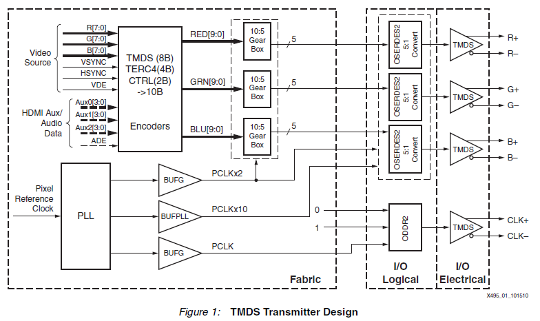
HDMI/DVI Video transmission over TMDS link is logically divided into stages as shown in the Figure 1: TMDS Transmitter Design of Implementing a TMDS Video Interface in the Spartan-6 FPGA

enter image description here

  1. TMDS encoders: convert pixel data from a video source, HDMI Auxiliary/Audio data, and HSYNC and VSYNC into three 10-bit symbol streams

  2. The serializers (10:5 Gear Box and OSERDES2 5:1 Convert) perform in two stages a 10-bit parallel-to serial conversion on all three streams and then send them out onto three channels of differential output pairs (TMDS buffers).

Both stages require a clocking circuitry to generate (PLL) and distribute (BUFPLL, BUFG) the clock signals (with frequencies of the pixel reference clock and its multiples) properly.

Of course, the core of the transmitter are the Encoders block. You can start with the DVI encoder due to its simplicity compared to the HDMI one. Both HDMI and DVI have many aspects in common, including the physical TMDS link, active video encoding algorithm and the control tokens definitions.

The application note also provides 2 designs. A simple but good for starting is the "SMPTE HD Color bar Generation with Programmable Video Timing". It sends a color bar generator video across many screen modes which can be selected by the slide-switches. This design is useful because we can change the color bar generator with another video source and still be able to get some video keeping the original transmitter block.

I hope this helps!

\$\endgroup\$
2
  • 3
    \$\begingroup\$ Link only answers are discouraged because if Xilinx reorganize their site in the future and the link becomes dead it won't be of any assistance to future visitors. Maybe you could add some extra details of the general approach the application note describes? \$\endgroup\$
    – PeterJ
    Commented Apr 28, 2013 at 10:43
  • \$\begingroup\$ Thanks, you are completely right. I have added some more details about it. \$\endgroup\$ Commented Apr 28, 2013 at 16:20
3
\$\begingroup\$

Here is the text of a reference design you can download from the board page you linked to:

DSD-0000326 12/13/11 This zip file contains an EDK demo project that demonstrates using HDMI on the Genesys board. It accepts an HDMI input, buffers the input frames into memory, and then outputs the buffer to another HDMI port. This is implemented using PLB bus. Download

You can also look at the reference designs that come with the Xilinx spartan 6 industrial video processing kit. http://www.em.avnet.com/en-us/design/drc/Pages/Xilinx-Spartan-6-FPGA-Industrial-Video-Processing-Kit.aspx (click on the support files link, avnet login required).

There are probably more reference designs out there for different fpgas as well.

Also unless you are implementing the audio or encryption hdmi is basically the same as dvi.

\$\endgroup\$
1
  • \$\begingroup\$ Thanks. I saw that but I'm not really sure how to use it since it uses EDK which I don't have because it isn't free. Would it be a simple matter of using the vhd files in it? I doubt it because there are quite a lot of other things in the download, most of which I have no idea what they are. \$\endgroup\$
    – ballaw
    Commented Mar 12, 2012 at 23:15
1
\$\begingroup\$

The following tutorial, making use of a miniSpartan6, is very detailed and worth a look: http://zerocharactersleft.blogspot.com/2015/04/diy-fpga-based-hdmi-ambient-lighting.html

\$\endgroup\$
1
  • \$\begingroup\$ Link only answers are discouraged because if the link becomes dead it won't be of any assistance to future visitors. Maybe you could add some extra details? \$\endgroup\$ Commented Jan 6, 2017 at 17:05

Your Answer

By clicking “Post Your Answer”, you agree to our terms of service and acknowledge you have read our privacy policy.

Not the answer you're looking for? Browse other questions tagged or ask your own question.