1
\$\begingroup\$

I have a project with several physical constraints so that I want to use: 1. A sealed very thin momentary switch as main on/off switch 2. 2 x AAA battery supply = 3V or less 3. Load is a small DC motor pulling max 0.3 amp 4. Momentary to Latching circuit to be as small as possible and with zero current drain in the off state

I have looked a various momentary to latching circuits using transistors, MOSFETS, and Flip Flops but as best I can tell they all have a very small drain current of approximately 10uAmp or more in the off state.

I am correct about the off drain current for these circuits?

If I am not correct can you suggest a circuit that would work for my project?

If I am correct does anyone have a circuit design that would meet true zero drain current for the requirements above?

Many thanks.

\$\endgroup\$
7
  • \$\begingroup\$ 10uA is not much, particularly if you are using 2xAAA cells, are you sure it's really a problem? \$\endgroup\$ Commented Jan 30, 2017 at 6:15
  • \$\begingroup\$ ti.com/lit/ds/symlink/ts5a9411.pdf maximum of 2 nA of leakage current (OFF state current too) \$\endgroup\$
    – User323693
    Commented Jan 30, 2017 at 6:19
  • \$\begingroup\$ How do you turn on this supply line switch? Is it a physical open/closed switch or under programmatic control? TI have some new ultra low leakage FETs with a maximum of 150 nA (combined Ids (@9v) + Igs(@4v)), these will likely be well less than 60 nA at 3 V. ti.com/lit/ds/symlink/csd17483f4.pdf ...but a long way from zero. \$\endgroup\$ Commented Jan 30, 2017 at 6:37
  • \$\begingroup\$ @RogerRowland - the device could be in location for over a year so I am concerned even a very low drain current would run down the batteries. \$\endgroup\$
    – 6Volts
    Commented Jan 30, 2017 at 9:57
  • \$\begingroup\$ The answer seems to be that there is not a zero current option but MOSFETs with leakage of less than 60 nA are available. \$\endgroup\$
    – 6Volts
    Commented Jan 30, 2017 at 9:59

2 Answers 2

2
\$\begingroup\$

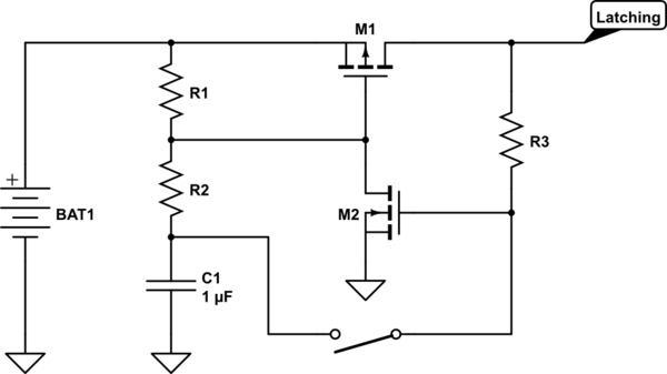
Depending on the requirements you could use a latching mosfet circuit as shown below. The first time you push the button M1 is turned on, the second time you push the button it is turned off.

When the circuit is off it does not consume power (other than leakage of the mosfet).

schematic

simulate this circuit – Schematic created using CircuitLab

\$\endgroup\$
2
  • \$\begingroup\$ The leakage current of the capacitor alone may dominate here, with most datasheet specifying about 200-500 nA for even the best electrolytic. \$\endgroup\$ Commented Jan 30, 2017 at 17:41
  • \$\begingroup\$ For this circuit a ceramic capacitor can easily be used. Those have far smaller leakage currents... \$\endgroup\$
    – Douwe66
    Commented Jan 30, 2017 at 18:12
0
\$\begingroup\$

Answering a comment on the csd17483fa.

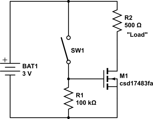
No, you don't need a P-Channel if you use a physical slide switch. Any other device you add will simply provide another leakage path that you don't want.

Using a simple slide switch seems the easiest path. You only contend with the Ids leakage of perhaps 60 nA or less.

schematic

simulate this circuit – Schematic created using CircuitLab

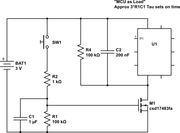
You could also use a push button to activate. Here I've shown an added capacitor which does not add to the leakage when off, so again only Ids leakage counts.

schematic

simulate this circuit

You could get creative and implement a way for an MCU to keep you powered on till you decide to shut off. However you have to be careful not to introduce other leakage paths in the process.

You should also note that even the best Alkaline batteries have a self discharge rate: https://na.industrial.panasonic.com/sites/default/pidsa/files/1.5vseries_datasheets_merged.pdf

Engineering much beyond about 3-5 years of battery life for an application is a real challenge. Shelf life for the batteries is predicted at only 7 years for 80% capacity, which would result in a terminal voltage decline to about 1.2 V per cell. The self discharge rate of course is highly temperature dependent which will impact operational lifetime.

\$\endgroup\$
2
  • \$\begingroup\$ I know this is long after the fact, but why add R4? \$\endgroup\$ Commented Oct 14, 2021 at 16:06
  • \$\begingroup\$ @SolderFumes R4 ensures that the voltage across the U1 falls at a predictable rate to close to zero. Ids leakage flows through R4. \$\endgroup\$ Commented Oct 15, 2021 at 0:25

Your Answer

By clicking “Post Your Answer”, you agree to our terms of service and acknowledge you have read our privacy policy.

Not the answer you're looking for? Browse other questions tagged or ask your own question.