2
\$\begingroup\$

I understand there have been quite a few posts asking about the DC motor speed vs PWM duty cycle issues. However, I found those questions different from what I want to ask, so I have to ask this topic again.

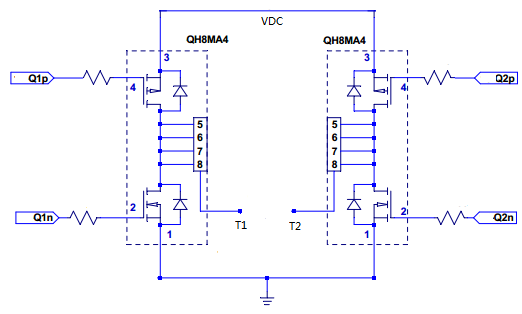
I have designed a circuit to drive a small DC motor as shown below. The P channels in the H-bridge are either Full-ON or Full-OFF depending which direction the motor rotates and the corresponding N channel is given PWM drive signals. The PWM frequency is 20kHz, VDC is 7V, T1 and T2 are connected to the DC motor terminals and the gate resistors used are 10 ohms.

In my understanding, the DC motor speed is supposed to be proportional to the drive voltage applied. So, if VDC is fixed, IMHO, the motor speed is supposed to be proportional to the PWM duty cycle because the motor drive voltage is VDC*PWM_dutycycle.

enter image description here

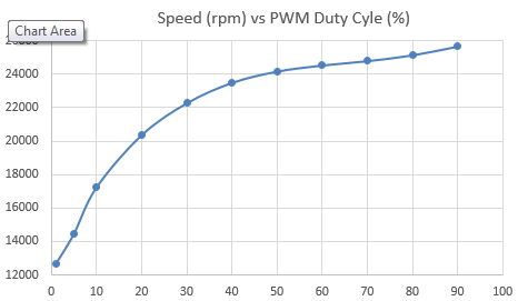
However, this was far from the actual case. Below is the speed vs duty cycle curve I recorded (picture updated).

enter image description here

When I fixed the PWM duty cycle but changed the VDC value, however, the motor speed became proportional to VDC*PWM_dutycycle.

Would anyone please advise why VDC*PWM_dutycycle could have different effects on motor speed when changing VDC compared to changing PWM duty cycle?

[update]

I forgot to mention that the motor shaft was connected to a gearbox whose reduction ratio is 290, and the speed shown in the above plot is the motor speed, not the gearbox output speed.

I started to wonder if this speed vs duty cycle issue was caused by the gearbox friction, which acted as motor load.

\$\endgroup\$
5
  • \$\begingroup\$ Say, Vcc=5V and D.T= 0.6. For a 1V-increase in the voltage while the D.T has been fixed, you get a 0.6V difference in the output. In the other hand, if you increase the D.T by 10 percent while the voltage is fixed, you get a 0.5V increase in the output. So either way will increase the average power delivered to the motor but with different amounts. \$\endgroup\$
    – dirac16
    Commented Feb 2, 2017 at 8:39
  • 1
    \$\begingroup\$ I understand your point, but if you look at the chart, 20% duty cycle and 40% duty cycle only resulted in 30% speed increase. For a 7V VDC, 20% duty means 1.4V, 40% 2.8V, shouldn't the speed be doubled as well? \$\endgroup\$ Commented Feb 2, 2017 at 8:48
  • \$\begingroup\$ From my understanding and the fact that real-life motors have resistance and a bunch of other things, it's not always true that the motor speed linearly changes with the supplied voltage. At some point, it may slightly start to show non-linear behavior. \$\endgroup\$
    – dirac16
    Commented Feb 2, 2017 at 9:03
  • 2
    \$\begingroup\$ What motor did you test (make/model, specs)? What rpm did the motor do on 7V direct? How did you determine the PWM ratio, and how did you manage to get over 500rpm with 0% PWM? What circuit is driving the lower FET Gates? Have you examined the drive waveform? \$\endgroup\$ Commented Feb 2, 2017 at 9:17
  • \$\begingroup\$ Hi, Bruce, I am sorry I made a mistake in the plot Y-axis unit and I have updated the picture in the post. The PWM ratio is controlled by MCU and we verified it using oscilloscope. The first test point could be somewhat misleading, but it was tested at 1% duty cycle. The P-channels were driven by another transistor and the N-channels are driven directly by MCU PWM outputs. I have observed the gate signals and motor terminal voltages and I think the MOSFETs are working properly. As for the motor spec, unfortunately, I don't have it. \$\endgroup\$ Commented Feb 3, 2017 at 6:27

1 Answer 1

1
\$\begingroup\$

The plot you shared seems quite similar to the one using diode freewheeling shown here. As you are using a H-bridge with active freewheeling I would guess that could be related to falling and propagation delays on the MOSFETs; during transitions you gonna have a period when only the diode is freewheeling. Try adding a dead-time on your PWM generation, you can use TIMx_BDTR for that matter.

From 1 it also seems like lower gate currents tend to add non-linearity, so changing the gate resistors for lower ones might help.

But, as you said, the gearbox fluid would add non-linearity. Try driving the motor without the gear and checking the speed. If speed control is paramount open-loop control is discouraged. Speed feedback using a encoder and PID algorithm controlling the PWM would be good approach, as seem here.

\$\endgroup\$
1
  • \$\begingroup\$ Also, the plot you share is also very similar to a current-torque curve of a electric motor. If the motor has load (something being driver by it) the RPM would be directly affected by the torque. If so, the curve in RPM x PWM is simply the motor nonlinearity. You can simply solve the problem by mapping those points on your software and interpolating for the desired RPM. The best solution would be close-loop control, by feeding the encoder output to your software and using a PID to control the speed. \$\endgroup\$ Commented Dec 28, 2020 at 15:14

Your Answer

By clicking “Post Your Answer”, you agree to our terms of service and acknowledge you have read our privacy policy.

Not the answer you're looking for? Browse other questions tagged or ask your own question.