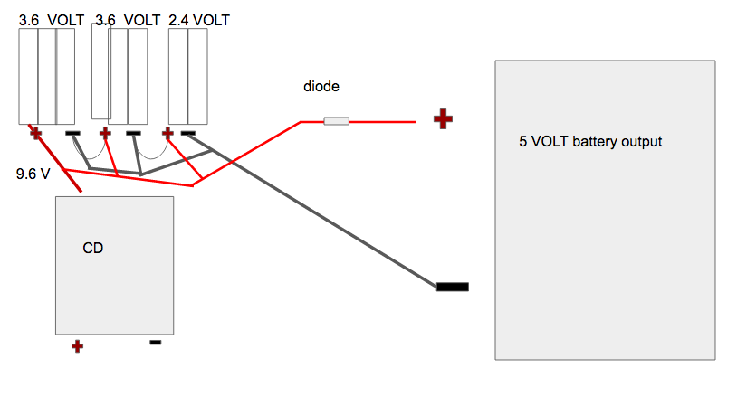
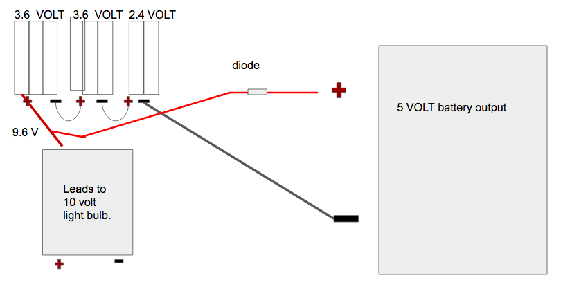
I know that when I am charging a battery, we need higher voltage than the battery is rated at in order to "push" current into the battery itself. Right? OK. Since that is true, is it possible for me to use a lower voltage, but into the separate battery packs? I WILL EXPLAIN. I am sending current into a 10 volt light bulb. The batteries I am using to send that current are eight 1.2V rechargeable aaa batteries (NI-MH) put into series. BUT I am using 3 battery holders, 2 of them hold 3 batteries, and one holds 2 batteries, as shown on the following pictures. So basically these battery holders are put into series. Now, when I charge them, how is the voltage distributed amongst all 8 batteries? Like, is the 5 volts going to go to each battery holder charging them individually, even thought they are in series? Is there a way I can charge this battery pack with 5 volts?  If this doesnt work, how about this?:
  Will each aaa battery get 5 volts, or each battery pack get 5 volts, or my whole setup get 5 volts? The reason I am asking this is because I know that in order to charge a battery you need higher voltage than it gives out, and a diode won't solve my problem of my setup won't work.
2 Answers
You could merge the two sets of 3 batteries and charge them in series with 7.2v (assuming they're balanced) but the pack of 2 batteries needs to be charged separately with a source of 2.4v.
Nevertheless, if you could remove the batteries it would be extremely recommended to charge each cell separately so they will be balanced and the risk of corrosion will be practically zero.
-
1\$\begingroup\$ You COULD theoretically charge them in parallel with a single 1.2v+ source, but it's not recommended for the harm it may cause \$\endgroup\$ Commented Feb 9, 2017 at 3:13
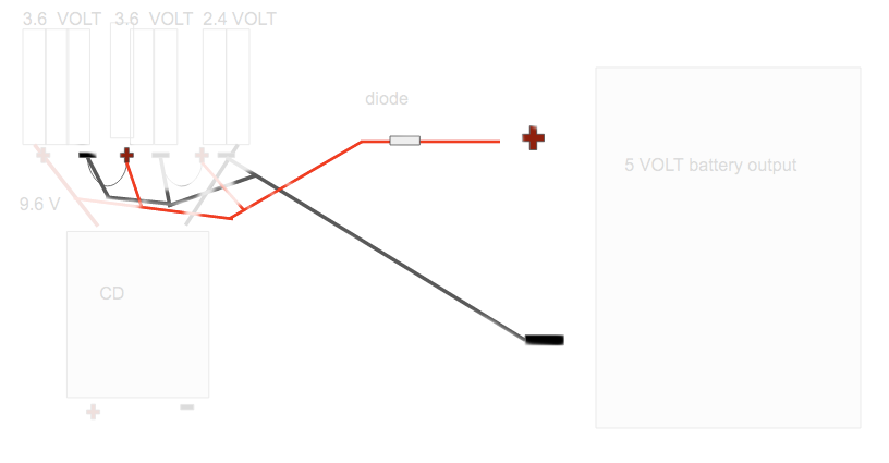
The first diagram doesn't work, since you'd have a short circuit (look at the red/blue lines near the interconnect between the two 3-cell holders - they are shorted through this interconnect):
The second diagram also doesn't work, since 5 volts is not enough to push charge through 8 cells; the voltage of the 5-volt battery would be lower than the battery pack, thus the diode will be reverse-biased.
If you do want a solution similar to your second diagram, you can use that, but provide higher voltage — around 12V — and place a series resistor instead of the diode. Select the resistor so that it limits the charge current to a lowish value when the pack is fully charged (20 mA or less is probably fine), since if there's no human around to monitor things, you'll continue pushing that current even when there's nothing more to charge, which only heats and degrades the cells. If the current were larger, the cells would be damaged quickly.
-
\$\begingroup\$ how is that a short curcuit. I dont understand. \$\endgroup\$– Ali RagbCommented Feb 9, 2017 at 17:46
-
1\$\begingroup\$ I've added a picture to clarify. \$\endgroup\$– anrieffCommented Feb 10, 2017 at 17:39
-
\$\begingroup\$ they arent touching though. The reason i drew them like that is because i couldnt draw them any other way. \$\endgroup\$– Ali RagbCommented Feb 10, 2017 at 17:47
-
\$\begingroup\$ whatch this video. please. Because it backs up my claim. youtube.com/watch?v=sN2mkvUOL5E \$\endgroup\$– Ali RagbCommented Feb 10, 2017 at 17:48
-
1\$\begingroup\$ It's not about the way you drew them, it's the connection topology. "+" from 5-volt goes to "+" on the second 3-cell holder. Through the interconnect it goes to the "-" of the first 3-cell holder. Then it goes to the "-" of the 5-volt. So it's a direct wire connection from "+" to "-" on the 5-volt: a subtle short circuit. The video shows nothing new - it's similar to your second diagram, which, as I said, will work, but you need higher voltage than 5 volts, and a current limiting resistor. The "12 volt car battery charger" shown in the video includes current limiting, so no resistor is needed \$\endgroup\$– anrieffCommented Feb 10, 2017 at 17:58

