1
\$\begingroup\$

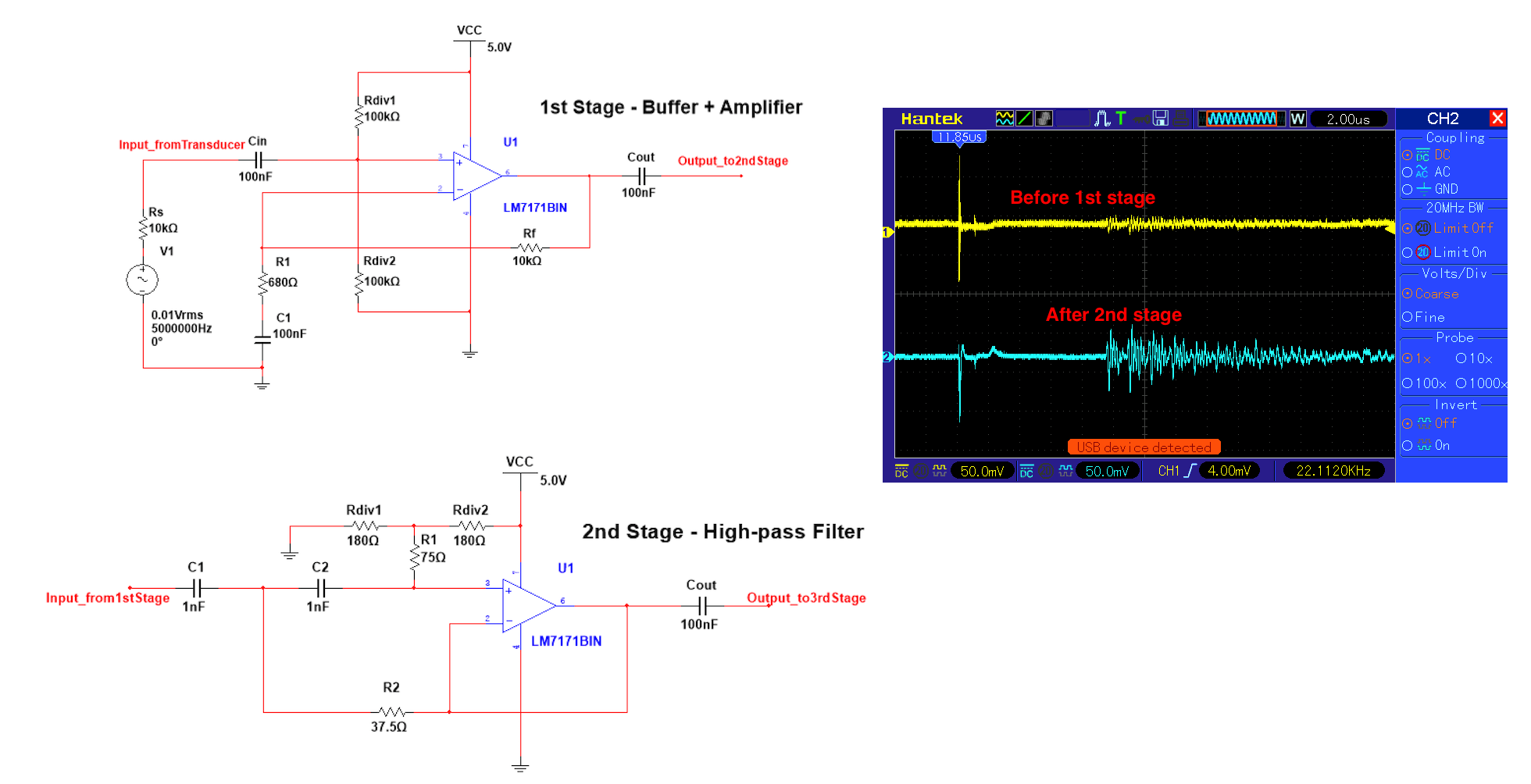
I am working on a project in which we are trying to design and build an ultrasonic thickness gauge that will calculate the thickness of a given part based on the time difference between sending a signal and receiving a reflection back (using the known speed of sound through the medium). We are currently using an Arduino nano as the MCU for our prototype. We have successfully amplified the pulse generated by the MCU to a higher voltage, which is then used to excite the ultrasonic transducer (which is in contact with the part that is being measured). The reflection is then detected by the second element of the transducer and converted into an electric signal that is centred around the natural frequency of the transducer (5MHz). This signal is then processed (amplified and filtered) into a level that will be detectable by the MCU (circuit and scope screenshot as shown below). However due to MCU's limited sampling rate, the signal will not be reliably detected. Therefore I was wondering if we would be able to devise an envelope detector that would extract the amplitude modulation of the reflection signal, effectively converting a very high frequency into a lower frequency signal, which I am hoping will be detected by the MCU.

enter image description here

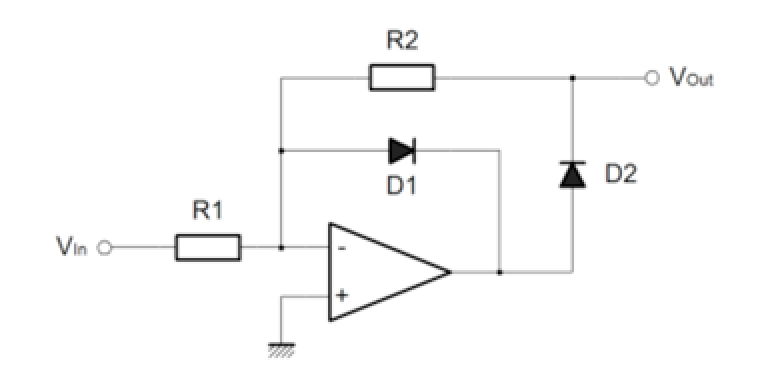
According to what I have read so far, this would be achieved by first rectifying the signal using a “super-diode” (precision rectifier configuration as shown below) and then integrate it through an op-amp integrator. However, it seems that because I am relying on single supply and the frequency of the signal of interest is very high, the rectifier will not work as I expected (op-amp used is LM7171, with very high slew rate 4100V/µs), in fact this particular design has proven useless with single supply, even though the very same op-amp has worked perfectly under a single supply arrangement for the circuits shown above. Is there perhaps a way of designing an envelope detector entirely from transistors instead of op-amps?

enter image description here

Any pointers or suggestions will be highly appreciated!

Thanks in advance

\$\endgroup\$
1
  • \$\begingroup\$ You will likely need a small cap across D1 \$\endgroup\$ Commented Feb 9, 2017 at 14:52

3 Answers 3

5
\$\begingroup\$

Having read the datasheet of LM7171, I have 7 suggestions:

0) is your scope fast enough (500MHz) to look for oscillations of the OpAmp

1) operate the OpAmp from 10Volts; its not characterized at only 5 volt VDD

2) use a Ground Plane

3) the datasheet says Rminvalue_feedback is 500 Ohms;

4) make sure your VDD bypass caps are 1mm (1/32") from the IC leads, or closer; use SurfaceMount bypass caps; to partially cancel inductance of PCB, place the GND via back under the bypass cap; current flows thru the cap and then must reverse and flow back a couple milliMeters, proving partial cancellation of L.

5) your rectifier circuit should work, but reduce the resistor values to up the rectification bandwith. The output node is not directly attached to the opamp, so the opamp cannot ensure the possible bandwidth is the achieved bandwidth; example: with 10pF on Vout, and 100Kohm Rfeedback, you have a 1uS tau and thus a 1uS PeakDetector.

7) to reduce risk of oscillation, place your resistors right next to the OpAmp IC; I worked with ADCs that oscillated (10milliVolts on -5.2 VDD at 900 MHz); and installing 33_ohm SMT R under the (bentup) Vin pin was the cure. Gate-stopper Rs are a safety factor in using power MOSFETS. A fast OpAmp also needs that respect for the gain-bandwidth it brings to your circuit; dampen its pins.

\$\endgroup\$
1
  • \$\begingroup\$ +6 but only one showed up :) \$\endgroup\$
    – uhoh
    Commented Feb 9, 2017 at 4:43
1
\$\begingroup\$

The reason for requiring the envelope detector, was that the ADC of the MCU can not sample fast enough, to detect the signal reliably. Let me propose another option which would work without a envelope detecor: Use a MCU which has an integrated analog comparator.

The analog comparator can be configured with external components, so that as soon as the input surpasses a certain voltage threshold, the comparator puts out a logic one. The MCU can then be setup to trigger an interrupt each time the comparator shows a rising flank. Even better: combine it with an internal timer which has a input capture function.

For example some AVRs are able to trigger the input capture function on a rising or falling edge from the analog comparator. The input capture stores the timer value at the moment of the edge and can additionally trigger an interrupt. When you substract the stored timer value (the time of starting the ultrasonic emitter), you have the required travel time.

\$\endgroup\$
1
\$\begingroup\$

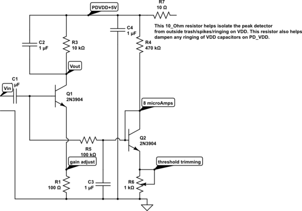
You also asked about an Envelope Detector using only transistors. I assume the 2 transistors have similar VBE at the same current. The pot allows some adjustment for threshold. If you cannot set Vout to be close to +5v when there is no input, then swap the 2 transistors. The "gain" will be the ratio of Rcollector(left NPN) / R_emitter(left NPN), with some scale factors involving area under a sinusoid. Why is there no Miller Effect here?

schematic

simulate this circuit – Schematic created using CircuitLab

\$\endgroup\$

Your Answer

By clicking “Post Your Answer”, you agree to our terms of service and acknowledge you have read our privacy policy.

Not the answer you're looking for? Browse other questions tagged or ask your own question.