2
\$\begingroup\$

While an ARM MCU is in deep-sleep mode it has to wake up from a normally closed input. (Driven by a reed switch.)

I use 2 methods:

  1. common to ground, input pin internally pulled-up and falling edge wakes the MCU.
  2. common to Vcc, input pin internally pulled-down and rising edge wakes the MCU.

Both works fine but it raises power consumption at about 100 μΑ.

Is there a solution with an IC that consumes zero power ?

\$\endgroup\$

2 Answers 2

3
\$\begingroup\$

I think a 0 power solution isn't possible with an NC contact. But you could reduce the power consumption by using a higher value for an (external) resistor, untill leakage and/or interference becomes a problem.

Can't you switch to a NO contact?

\$\endgroup\$
3
  • \$\begingroup\$ I already have a NO contact but I need a NC as well. Higher external resistor is an option but still consumes. I hope I could find an IC that could do the job \$\endgroup\$
    – TBELO
    Commented Feb 11, 2017 at 16:18
  • 1
    \$\begingroup\$ How could it? To detect whether the contact is still closed, it must carry a current, and a current doesn't come free in our voltage-oriented world. \$\endgroup\$ Commented Feb 11, 2017 at 16:37
  • \$\begingroup\$ You are so right Wouter! I have just seen an old post at eetimes.com/document.asp?doc_id=1272463 but I don't have the components to test it \$\endgroup\$
    – TBELO
    Commented Feb 11, 2017 at 16:47
2
\$\begingroup\$

As Wouter said, use the highest value pullup (or pulldown) that overcomes the maximum leakage current and still meets the digital input threshold requirements. 100 kΩ is acceptable with with most microcontroller inputs, for example. That would draw only 33 µA with a 3.3 V supply. Check the datasheet to see what is required in your particular situation.

Another possbility is to use a transistor to amplify the current:
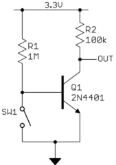
This only draws 3.3 µA continuously when the switch is closed. It will draw more when the switch is open.

Yet another strategy is to switch the sense circuit on only for brief periods when needed. Instead of the top rail in the circuit above being the 3.3 V supply, it would be tied to a digital output instead. The micro would sleep most of the time, then wake up periodically to test the switch. It would raise the digital output, wait a µs or a few for OUT to settle, take a reading, and power down the circuit again.

Waking up every 50 ms, for example, will still catch a new switch state instantaneously in human time. With a micro that has low sleep current, the average current draw can be under one micro-amp.

\$\endgroup\$
1
  • \$\begingroup\$ Thanks a lot for your answers. I 'll experiment with maximum possible resistor and I ll be back to post it! \$\endgroup\$
    – TBELO
    Commented Feb 11, 2017 at 20:23

Your Answer

By clicking “Post Your Answer”, you agree to our terms of service and acknowledge you have read our privacy policy.

Not the answer you're looking for? Browse other questions tagged or ask your own question.