1
\$\begingroup\$

Is it possible to amplify AC signal with In Amp in Single Supply, however, with a sufficient reference to 'compensate' the negative part of the signal?

I believe that a in amp with a single supply, for example 5V and GND, can not amplify negative signals because the power is not symmetrical. Right? Or not?

My point is:

If I add a reference (Pin 5) that makes the signal completely positive, is it possible to amplify this signal? Having as a result a fully positive amplified signal?

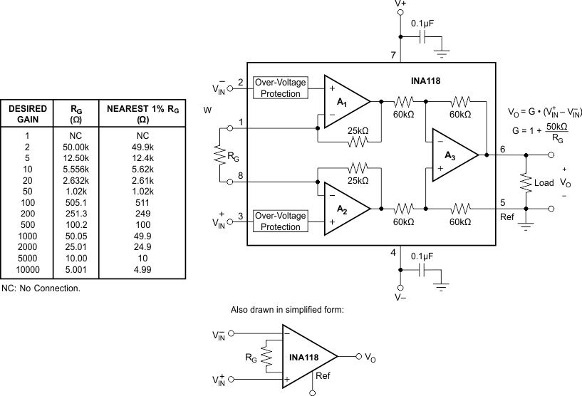
I'm using a in amp (INA118) with single supply (GND on pin 4 and 5V on pin 7) with gain equal to 2 (Rg = 50KOhm). On reference pin 5 I'm adding + 2.5V (Vdd / 2).

enter image description here

In my project, I need to inject a 1mA electric current into the patient's body through 2 electrodes, receive this signal through 2 other electrodes, and amplify this signal. Like This. The sine is a sinusoid of 1.98V pp and 1mA (With a frequency sweep from 1KHz to 100KHz) with the voltage ranging from -0.99V to +0.99V. The Schematic is like this.

\$\endgroup\$
2
  • \$\begingroup\$ Can you string the complete diagram together, please: current source,.. patient,.. InAmp?.. Reference electrode, perhaps?.. You are not leaving that to us, are you? \$\endgroup\$ Commented Feb 17, 2017 at 0:28
  • \$\begingroup\$ Nick, The Schematic is like this: i.sstatic.net/PU6cr.png I will use o AD5933 and a HPF (High pass filter or Capacitor Block DC), in the output of the HPF, the voltage will be 1.98V pp (-0.99V to +0.99V). The current source use two opamps (AD8606 with single supply +5V), the outputs of the current source (E1, E2) are the 2 current eletrodes, Z represent the patient's body, and E3, E4 are the two voltage electrodes. The AD5933 is a Sine wave generator and a ADC. \$\endgroup\$
    – VF35468
    Commented Feb 17, 2017 at 1:22

1 Answer 1

3
\$\begingroup\$

I believe that a in amp with a single supply, for example 5V and GND, can not amplify negative signals because the power is not symmetrical. Right? Or not?

Correct, this won't work. The full range of the input has to be bounded within the power rails of the InAmp. In fact it's a little tighter than this if you look at the data sheet.

If you look on page 5 it tells you the "linear input voltage range" and this is restricted to typically -Vs + 0.95 volts and +Vs - 0.65 volts. In your situation, with a 0V and 5V rail, the input range is +0.95 volts to +4.35 volts. No amount of fiddling with the ref pin is going to alter this.

There are similar restrictions to the output voltage range too.

\$\endgroup\$

Your Answer

By clicking “Post Your Answer”, you agree to our terms of service and acknowledge you have read our privacy policy.

Not the answer you're looking for? Browse other questions tagged or ask your own question.