1
\$\begingroup\$

Regarding Altera's MAX10 Cpld, I got some questions regarding the interface of this CPLD with 3.3V devices.

I have set pins to 3.3V LVCMOS and I got this warning message in quartus: "Warning (169177): 100 pins must meet Intel FPGA requirements for 3.3-, 3.0-, and 2.5-V interfaces. For more information, refer to AN 447: Interfacing MAX 10 Devices with 3.3/3.0/2.5-V LVTTL/LVCMOS I/O Systems."

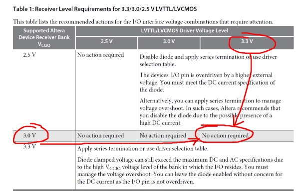
Looking at the AN447 document, it mentions on page 2enter image description here

To my understanding, if VCCIO is set to 3V, there is no need for anything to be done when it comes to interfacing with a 3.3V device.

But that makes little sense to me, I don't understand the reason why when VCCIO = 3V, then all issues are solved:

  1. Why bothering using 3.3V as VCCIO then, why the trouble?
  2. Could anyone confirm I'll be fine interfacing directly with a 3.3V device when VCCIO = 3V?

Thanks for your inputs. I'm sure there is a big misunderstanding there and I want to clear that out.

\$\endgroup\$

2 Answers 2

1
\$\begingroup\$

With an un-terminated line that is long enough and driven fast enough, there is a potential for overshoots with voltage level high enough to exceed the rating of a MAX10 input.

There is a "PCI clamp diode" for each MAX10 I/O pin that can clamp the voltage. The clamp diode is connected between the pin and Vccio (AN447 figure 2). Therefore the voltage is clamped to Vccio + V_forward_of_diode. At Vccio=3.3V, the clamped voltage is still high enough to exceed the rating of the pins. At Vccio=3.0V, the clamped voltage is low enough.

With Vccio=3.0V, the MAX10 I/O should interface with 3.3V without issue. The Voh could be lower than when Vccio=3.3V, but it should still be high enough for 3.3V logic that I know of. Of course, verifying an interface matches in levels is part of the design process regardless of whether using 3.0 or 3.3V as Vccio.

Some possible reasons for using 3.3V instead of 3.0V:
3.3V is already required somewhere else, so using 3.0V creates a requirement for an extra voltage source.
Lines are short enough or not driven hard enough that overshoot is not an issue.
When overshoot can be an issue, controlling it with series termination may be preferred anyway because that also reduces EMI effects.

\$\endgroup\$
4
  • \$\begingroup\$ Thanks for your answer. May I have possibility to feed VCCIO with 3V instead of 3.3V, you recommend I go for VCCIO = 3V instead of 3.3V? Then I should set the I/O to 3.3VLVTTL inside quartus. Right? Thanks. \$\endgroup\$
    – ggadde29
    Commented Feb 28, 2017 at 20:34
  • \$\begingroup\$ If 3V is available, usually there is no reason not to. You should set the I/O to 3.0V LVTTL to match the Vccio actually used so that Quartus would use the correct parameters. If a number of inputs have strong overshoots, consider other measures (e.g. series termination) and not just rely on the clamp diodes. For example, a 16-bit bus coming in with all 0 to 1 transition can dump a lot of current through the clamp diodes if strong overshoots are present. \$\endgroup\$
    – rioraxe
    Commented Mar 1, 2017 at 1:19
  • \$\begingroup\$ Thanks for the details. Just to make it clear: If I interface the MAX10 with a 3.3V device (eg. A flash memory). It's better and safer to feed VCCIO with 3V and set the I/O to 3.0LVTTL. \$\endgroup\$
    – ggadde29
    Commented Mar 2, 2017 at 6:01
  • \$\begingroup\$ Yes. But for reliable operation, you don't want tendencies of strong undershoot or overshoot even if damage is not an issue, either by placing the memory close to the FPGA or other methods. \$\endgroup\$
    – rioraxe
    Commented Mar 2, 2017 at 10:51
1
\$\begingroup\$

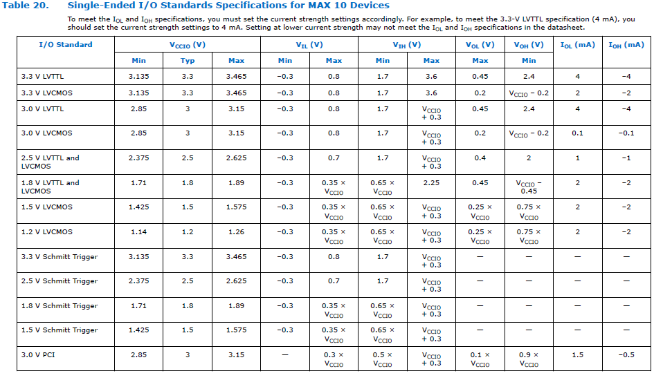
See this table from the datasheet (sorry its small, click on it for a better view). The table is the same for LVTTL with the exception of \$ V_{OH} \$ which would be 2.8V (which is still larger than 2.4V) so it really wouldn't make a difference for almost all applications.

For LVCMOS however the current requirements are different between 3.0V and 3.3V. So there will be fanout differences between 3.3V and 3.0V.

Other than that there are a few hysteresis timing differences between 3.0V and 3.3V for Schmidt triggered outputs.

It should be fine in most applications interfacing 3.0V and 3.3V. Since there is variability in devices, its a good idea as a digital designer to check each output pin and when the pin is 'on' check the Voh and make sure its going to meet the minimum Vih of the receiving devices logic. Same thing when its 'off' with Vol and Vil. Then check the fanout current and make sure you have enough current to drive the receiving device (or devices) current requirements.

Another note, Quartus needs to know what the voltage level is for at least three reasons:
1) So it can select the appropriate pull-up resistor
2) So it can set the right PCI clamp diode
3) So it can determine receiver timing with the included tools.
enter image description here

Fanout won't damage the chip (if you have a Voh and too much load it will drop the voltage). Overvoltage can. You can see that the 3.3V LVCMOS and LVTTL have a Vmax of 3.6V, don't exceed that. For 3.0V LVCMOS and LVTTL Vmax is 3.3V, so its right on the boundary and there is no margin, I wouldn't be comfortable with that as a designer if I had a low impedance source. If the input goes above (its a diode curve so the higher it goes the more current it draws) 3.3V then the diode will turn on and start sinking current, how much current depends on the source (device). It becomes a problem if the diode heats up beyond its thermal rating. So if you can keep it below the tables recommended 3.3V for a 3.0V voltage then you are good to use a 3.3V device.

In the past with microcontrollers I've used current limiting resistors or external diodes (or both) to limit current when the input voltage is too high.

As far as overshoot goes (which means short transitions) , the datasheet says this, so in the short term the inputs can take some abuse:

1.1.1.2 Maximum Allowed Overshoot During Transitions over a 11.4-Year Time Frame During transitions, input signals may overshoot to the voltage listed in the following table and undershoot to –2.0 V for input currents less than 100 mA and periods shorter than 20 ns. The maximum allowed overshoot duration is specified as a percentage of high time over the lifetime of the device. A DC signal is equivalent to 100% duty cycle. For example, a signal that overshoots to 4.17 V can only be at 4.17 V for ~11.7% over the lifetime of the device; for a device lifetime of 11.4 years, this amounts to 1.33 years.
\$\endgroup\$
2
  • \$\begingroup\$ Thanks for your answer. Maybe I wasn't clear enough but my question was more about the overshoot issue mentioned in AN447 (when toggling the pin quickly). To me the document says having VCCIO = 3.3V and interfacing with 3.3V device requires additional series resistor protection. While your post seems to say that VCCIO with 3V or 3.3V is not a big deal besides the level and fanout issues (wont damage the chip). To my understanding, having VCCIO =3.3V and interfacing with 3.3V device will damage the I/O if no extra protection added. \$\endgroup\$
    – ggadde29
    Commented Feb 27, 2017 at 18:54
  • \$\begingroup\$ I didn't see the word overshoot anywhere in the original OP, so maybe that is why I didn't say anything about it. I've edited my question. \$\endgroup\$
    – Voltage Spike
    Commented Feb 27, 2017 at 20:35

Your Answer

By clicking “Post Your Answer”, you agree to our terms of service and acknowledge you have read our privacy policy.

Not the answer you're looking for? Browse other questions tagged or ask your own question.