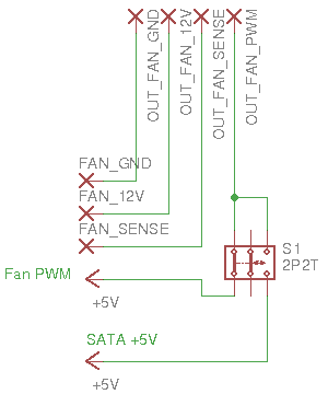
I am just getting into electronics, and I thought I knew enough to make a simple fan control circuit. The idea is that I can install a switch into my PC case that I can press in order to add a fan boost.
Initially, I was going to simply cut the PWM signal from the fan off, which would make all fans spin at max (according to an Intel spec). However, I learned that water cooling pumps don't necessarily follow the same behavior. As I also want water cooling when I build my new desktop, I cannot simply cut the PWM -- I have to generate a 100% duty cycle 5V PWM signal -- a steady 5V, as I understand it.
In light of this issue, I opted to use the 5V power from a SATA connector to emulate the 100% duty cycle PWM signal since I can't see any way to convert the PWM signal into a steady 5v without a DAC followed by a boost converter -- which is a little out of my level of understanding at the moment and wouldn't function if, for some reason, the PWM was at 0%.
In the diagram above (I am just starting to figure out Eagle) the left-hand pins are a fan input (ideally from the motherboard) and the pins at the top are the fan output pins. A 4-pin fan header cable will be run from this device to a PWM splitter, making this the PWM master for all fans/pumps.
I have a couple of questions regarding this circuit:
Would this circuit be considered safe? It is my understanding that I should also be using a SATA ground connection since I'm using the SATA 5V, but by my reckoning, when the switch is to the right, the fan circuit should provide the ground. If this is correct, is there a potential risk of overcurrent of the fan pins on the motherboard due to the fact that the 5v didn't originate from the fan pin header?
Also, I considered adding the SATA ground and tying it to the fan ground and perhaps adding a resistor right after the FAN_GND input in order to persuade the current to flow back into the SATA ground instead, but would this be likely to cause problems?
For the experts here, are there any other aspects that I haven't considered here? Any potential problems that I might arise if I were to build this as a circuit right now (I don't have the equipment to build this at home at the moment, so I can't physically test it)?

