1
\$\begingroup\$

Updates after applying Trevor's advice: I have attenuated the output of the CPS to between 2 and 2.5 volts, as shown in the scope pic: enter image description here, channel 2 is the constant "high" output from the schmitt trigger, which is not connected to any input in that screenshot.
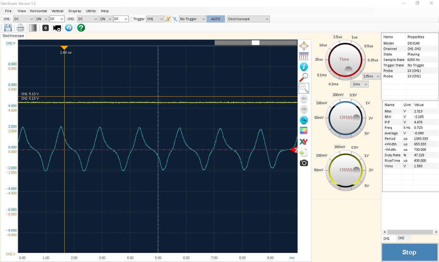
the issue now is that when I connect the trigger input it drops the voltage way down and the scope looks like this: enter image description here
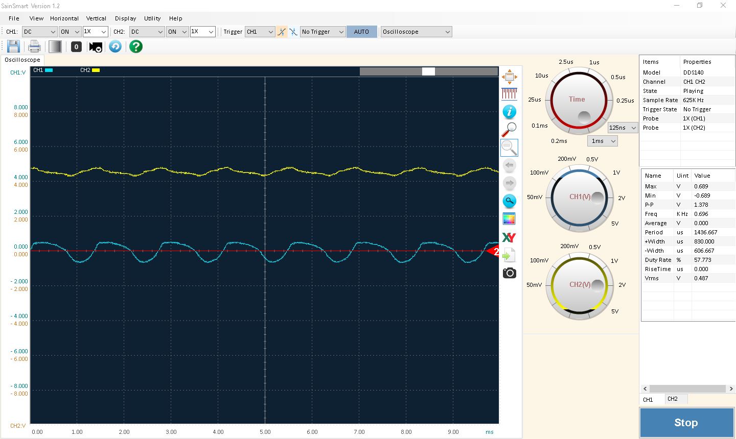
I have absolutely no idea why it is dropping the voltage so much, any advice on what to change? see Trevor's answer for schematic.


original question below:

I am an ME lost in a EE world... Overall problem is need RPM input from an engine to an arduino for PID control. Went to the shack and picked up some stuff to experiment with. Seems that the LM339 should be able to pickup the peaks of the analog signal from the crank position sensor and output a logic signal that the arduino can count and convert to rpm.

I have referenced the TI datasheet and application guide [see figure 6] in my efforts so far. See attached schematic for my starting point. Also attached the scope reading of the analog signal from the cps.

My question is basically can this work or am I missing some fundamental EE reasoning? Input/advice on resistor values, decoupling caps, and the proper Vref value would also be greatly appreciated.

would not let me post links to the application guide or my search results, found some info on decoupling caps for IC's but not sure how to apply it to my circuit.

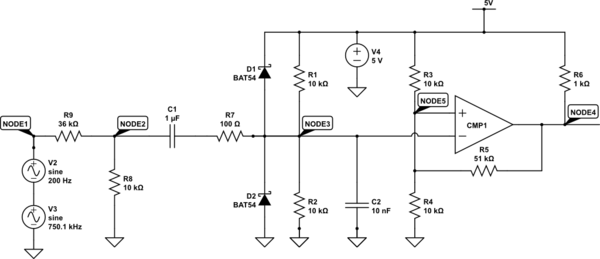
\$\endgroup\$
3
  • \$\begingroup\$ is the peak amplitude always the same +/-1V ?? also what is lowest cycle/s? \$\endgroup\$
    – D.A.S.
    Commented Mar 17, 2017 at 19:39
  • \$\begingroup\$ take a look at this circuit i1251.photobucket.com/albums/hh558/nemo4all/… \$\endgroup\$ Commented Mar 17, 2017 at 19:53
  • \$\begingroup\$ Great question! You've obviously done your homework. \$\endgroup\$
    – pipe
    Commented Mar 17, 2017 at 20:51

5 Answers 5

4
\$\begingroup\$

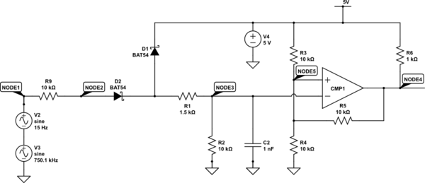
The circuit below should do the trick.

I A.C. coupled the input signal and biased it to 2.5V using C1 and R1, R2.

Shotky diodes D1, D2, with R7 afford you protection in case the signal ventures over 2.5V peak to peak.

C2 provides some noise filtering. You may need to adjust this size to best suit your application

The reference is set on the plus pin at 2.5V with about +/- .44V hysteresis. If the signal has a ripple or noise larger than that decrease the size of R5.

R6 provides the final pull-up.

schematic

simulate this circuit – Schematic created using CircuitLab

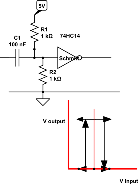
enter image description here

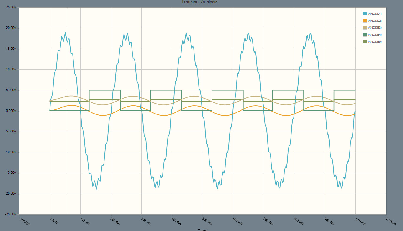
EDIT: Since your input signal is a lot larger than you originally intimated, You could also use the following circuit to simply half-wave rectify it and attenuate it a little.

Benefit of this method is you pretty much guarantee full swing on the input of the comparator. That allowed me to decrease R5 giving you more hysteresis and lowered C2.

schematic

simulate this circuit

\$\endgroup\$
13
  • \$\begingroup\$ Trevor, thanks so much for the help, we tested this with a 1.6v battery and at least got a high output, however, before we hooked it up to the engine we decided to scope the connections one more time, since we did not do it initially... trust but verify. Turns out they had 1x set on scope and 10x set on probe so voltage is actually oscillating between +18 and -16 or so. So now we are back to drawing board, would your schematic scale that much? \$\endgroup\$ Commented Mar 18, 2017 at 2:23
  • \$\begingroup\$ Try the extra divider on the front as I edited. @NathanWolanin \$\endgroup\$
    – Trevor_G
    Commented Mar 18, 2017 at 3:15
  • \$\begingroup\$ Just got to the shop, getting after it now. How critical is it to use those exact diodes, 1N5817? The closest I have on hand is 1N4001. Also, can I use a tantalum cap for the 1 microfarad cap in the beginning? I can go to the shack again if necessary, its not too far away. \$\endgroup\$ Commented Mar 18, 2017 at 22:04
  • \$\begingroup\$ These diodes are schotky diodes, they have a smaller forward voltage though the exact model# isn't too critical here. You should not use a Tantalum though, they are polarized, use a ceramic capacitor or similar instead. \$\endgroup\$
    – Trevor_G
    Commented Mar 18, 2017 at 22:17
  • 1
    \$\begingroup\$ edited original post to show scope from your circuit. It looks like I have dropped the input voltage too much, looks to be about 1 volt. going to reduce the original voltage divider some and see what that does. \$\endgroup\$ Commented Mar 19, 2017 at 2:47
2
\$\begingroup\$

The LM339 won't like inputs that drop below 0 volts. The absolute maximum negative input voltage is -0.3 volts below the negative power supply rail.

I would consider biasing the input signal to somewhere between the power rails. It might be an issue if the RPM is low but I don't think you have much of an option. Some comparators (like the MAX999) are designed to be used with a negative input signal but this still has to be restricted and I would consider using a potential divider to reduce the input signal to +/- 75 mV.

Your pull up resistor is also far too low and implies an amp of current into the device when driving a low output signal. The MAX999 (and others) have a push pull output and don't require this resistor. Looking at the hysteresis resistors I think you have too much hysteresis, so much that the input signal won't be able to switch the output from one state to the other.

\$\endgroup\$
1
  • \$\begingroup\$ If the sensor is the inductive type, it has no ground reference; you can connect both wires at will, which simplifies biasing. If the sensor were the Hall type, it might need no gain stage. \$\endgroup\$
    – Whit3rd
    Commented Mar 17, 2017 at 20:18
0
\$\begingroup\$

Suitable for signals 2Vpp with 500 Ohm load to reduce stray noise coupling. Use twisted pair , pref shielded from Arduino gnd side only.

schematic

simulate this circuit – Schematic created using CircuitLab

\$\endgroup\$
0
\$\begingroup\$

If you feed a voltage below about -0.6V to LM339 inputs, then a high current will flow out (limited by your sensor) and LM339 input stage may not survive.

Simplest solution is to stick a resistor in the input, like 10k, and let the input protection diodes shunt the current to GND.

A much better solution, especially near motors which may create lots of noise, is:

  • Use hysteresis
  • Filter input signal

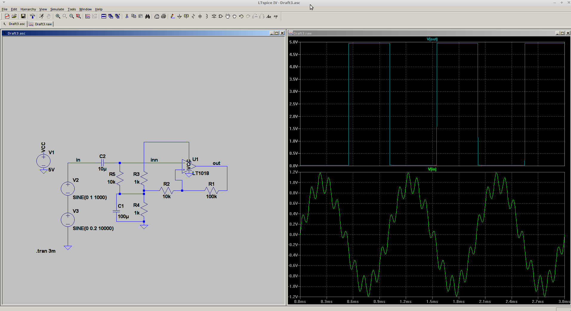
Here's a quick example. Here, I set hysteresis high enough to reject the noise on the 1kHz waveform. You can use LM339, I used LT1018 here because the model comes with LTSpice.

enter image description here

See how comparator ignores multiple zero crossings due to hysteresis?

A small RC filter on the input signal to get rid of HF noise is also a good idea.

\$\endgroup\$
0
\$\begingroup\$

can this work...

the basic concept is sound, aside from excessive positive feedback.

in cases like that, the challenge often is a signal with varying degrees of "average". so you cannot "pre-set" the reference voltage.

if your application calls for that, you may think about how to take that on.

\$\endgroup\$

Your Answer

By clicking “Post Your Answer”, you agree to our terms of service and acknowledge you have read our privacy policy.

Not the answer you're looking for? Browse other questions tagged or ask your own question.