0
\$\begingroup\$

I am testing time constants for a capacitor. Practical implementation is almost accurate as theoretical calculation. But the Time const changes(rises) when I introduce an LED in series with R AND C.

cap=1000uF; Res=10K; Vcc=5V; When only Cap and resistor is present, the Time constant comes out to be 10sec at 63% of vcc which is ~3v1 and practically it comes out to be ~11sec so it's okay.

But when I introduce 2v2 Red-Led in series with it, the time const rises to 30sec. As far as I know, LED has internal resistance in mili-ohms so the R will not be the reason for this much change.Other factor is the LED capacitance, It will probably have some value but that value should reduce the Time constant instead of increasing it because it is in series with the 1000uF so the overall capacitance should be low, hence (RXC) should be low.

Am I missing something?

\$\endgroup\$
2
  • 2
    \$\begingroup\$ How are you measuring time constant? Over most of the range the LED is dropping 2.2 volts so time constant is from 0V to \$ (5 - 2.2) \cdot 0.63 = 1.764 \$ volts not \$ 5 \cdot 0.63 = 3.15 \$ volt. \$\endgroup\$ Commented Mar 27, 2017 at 9:11
  • \$\begingroup\$ @WarrenHill : Thanks for the reply and you are right. I thought 2v2 of led will exist only at t=0 and it will gradually reduces to 0V as the capactor, but I found that capacitor will only see 5-2v2. Practically, led drops to ~1v7 and it just stop there, i calculated for 5-1v7 and it's value comes out to be true. \$\endgroup\$ Commented Mar 27, 2017 at 9:53

2 Answers 2

3
\$\begingroup\$

An LED is not a resistor! Simple as that.

It is a totally non-linear device. Look for I/V curves of diodes to understand what I mean:

Diode IV Curve
(by H1Voltage from Wikimedia Commons)

A resistor would be a perfect straight diagonal line through the origin point with the slope being the resistance.

That means that for low voltages, the "apparent" ohmic resistance is large, and for high voltages very low. For negative voltages (which can be often involved when one is concerned with things like step responses), we typically even model diodes as perfect isolators (R going to infinity).

Especially, that means that you can't just go and say "hey, that's the time constant of my R-C-LED circuit", since unlike RC circuits, you can't just scale the input voltage and get a simply scaled output. A diode is a nonlinear device!

So, most probably that means you're trying to calculate/simulate/measure a number that's practically meaningless.

\$\endgroup\$
1
  • \$\begingroup\$ That is helpful, so practically it isn't possible to accurately measure the time requirement to charge capacitor in this scenario but I observed that the time required for a capacitor to charge at 63% of (Vcc-Vled) is very close to the RC circuit. \$\endgroup\$ Commented Mar 28, 2017 at 4:55
1
\$\begingroup\$

Am I missing something?

charging up a R/C/LED circuit at Vcc is very much like charging up a R/C circuit with Vcc-Vfwd where Vfwd is the forward voltage of the LED.

So 63% of Vcc in this case (about 3 V) should really be compared to time constant of 3 V under a Vcc of 5 V - 2.2 V = 2.8 V < 3 V. Which is very very long, as you observed.

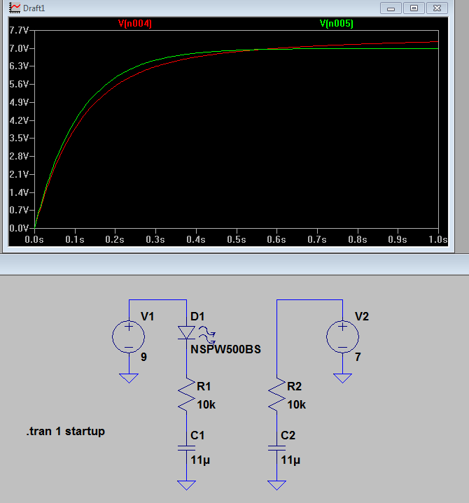
edit: here is a quick simulation that may help explain the difference between a rcled and rc circuit.

The circuit on the right is a rcled being charged up at 9v. the circuit on the right is its equivalent rc circuit being charged at Vcc - Vfwd. The curves are roughly the same - but not exactly due to the much higher equivalent resistance of the led as charge current slows down.

hope it helps visualize it for the OP.enter image description here

\$\endgroup\$
3
  • \$\begingroup\$ I do agree on the "should be compared to the difference between supply and diode forward voltage" part, but not to the "is very much like charging up a RC circuit with that voltage part", since, as my answer strives to compare, it's not. \$\endgroup\$ Commented Mar 27, 2017 at 10:12
  • \$\begingroup\$ Practically I observed that the LED voltage drops to about 1v5 and now it is decreasing with a very very low rate. took ~15min to drop to 14v2 \$\endgroup\$ Commented Mar 27, 2017 at 11:18
  • \$\begingroup\$ That's correct. The capacitor will actually charge all the way to vcc, if you are willing to wait long enough. The key here is to think of the diode as a resistor whose resistance is negligible when there is a meaningful amount of current through the diode. As the current drops the voltage across the diode drops but at a slower rate than the diode so the equivalent resistance of the diode goes up. \$\endgroup\$
    – dannyf
    Commented Mar 27, 2017 at 11:51

Your Answer

By clicking “Post Your Answer”, you agree to our terms of service and acknowledge you have read our privacy policy.

Not the answer you're looking for? Browse other questions tagged or ask your own question.