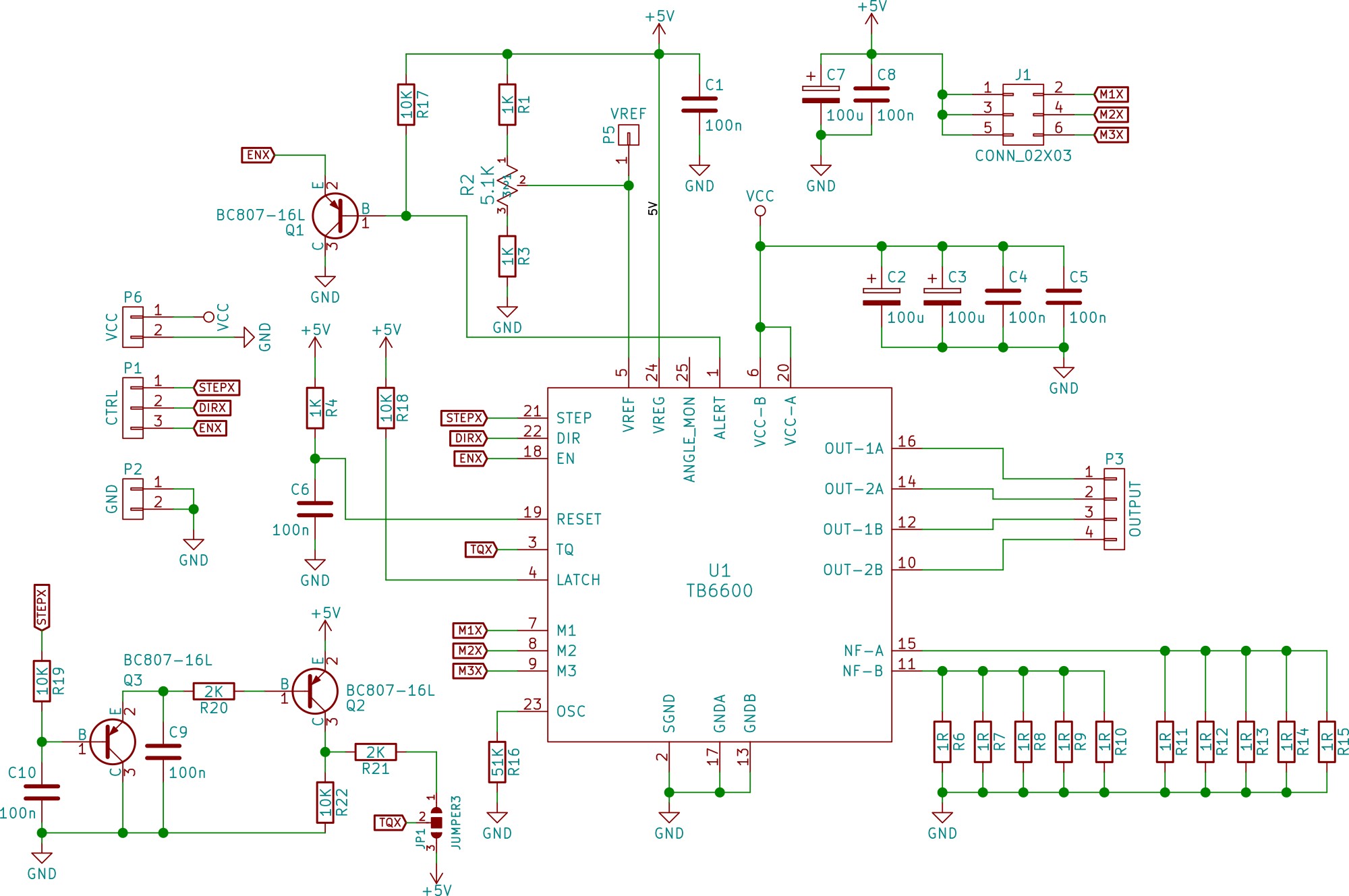
I've been working on this TB6600 design (schematic shown here). Q1 ensures that the motor remains within the current limits. The TB6600 drives the ALERT pin low when the current limit is exceeded. Q2 and Q3 are for the torque control. IF there is a step of continous pulses the TQ pin is held high and hence maintain 100% torque. Current sense resistors are 5 x 1R 1W resistors. VCC is 24V and stepper resolution is set at 1/16.
However this does not seem to be working. The motor moves a little and stops.
Here is the code I'm using to test the motor (a NEMA 23 stepper motor rated at 2.8A). The code is supposed to drive the motor through 200 steps and hence make one full circle. However, that does not work. I also tried driving this with grbl but I get the same results. What am I missing?
// defines pins numbers
const byte dirPinX = 5;
const byte stepPinX = 2;
const byte enablePin = 8;

void setup() {
  // Sets the two pins as Outputs
  pinMode(dirPinX, OUTPUT);
  pinMode(stepPinX, OUTPUT);
  pinMode(enablePin, OUTPUT);

  digitalWrite(enablePin, LOW);
}

void loop() {

  digitalWrite(enablePin, HIGH);

  digitalWrite(dirPinX, HIGH); // Enables the motor to move in clockwise direction

  for(int x = 0; x < 200; x++) {
    digitalWrite(stepPinX, HIGH);
    delayMicroseconds(500);
    digitalWrite(stepPinX, LOW);
    delayMicroseconds(500);
  }
  delay(1000); // One second delay

  digitalWrite(dirPinX, LOW); // Enables the motor to move in anti-clockwise direction

  for(int x = 0; x < 200; x++) {
    digitalWrite(stepPinX, HIGH);
    delayMicroseconds(500);
    digitalWrite(stepPinX, LOW);
    delayMicroseconds(500);
  }
  delay(1000); // One second delay

}

