I am trying to repair a broken toy car (a Bee-bot to be exact).
Each of it's two motors controlled by H bridges. One of the motors runs correctly both forward and reverse. The other motor runs only forward.
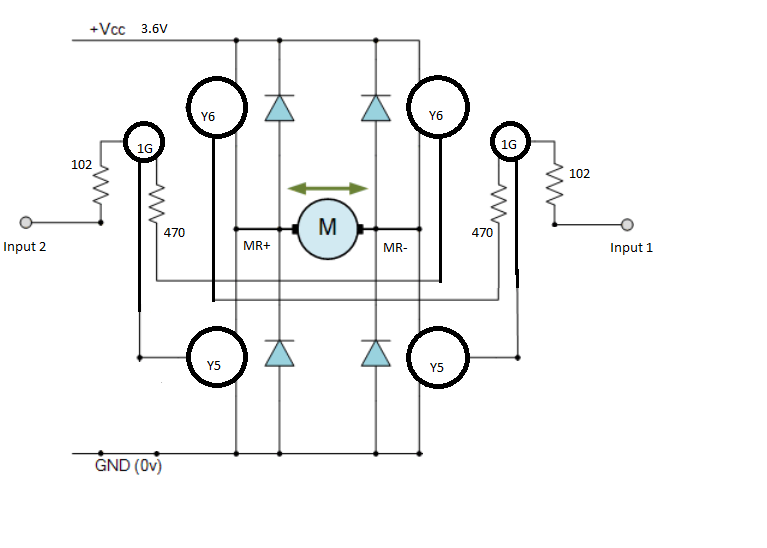
I believe the schematic is as such (for one motor):
I do not know what Y6, Y5 and 1G is but I assume they are transistors.
Since it has two identical bridges (one for each motor), with one of them working, I can easily compare them.
The signals are confirmed to be accurate low or high, and the motor is running fine in both direction with powered by another source.
When input is applied to input 1 on the GOOD bridge (motor runs fine), I get these voltages:
- MR+: 0.3V
- MR-: 3.3V (this is a bit counter-intuitive to me - feels like it should be the opposite? have I measured wrong somehow)?
- Between Y5 (near MR-) and 1G: ~0.5V
When input is applied to input 1 on the BAD bridge (motor does not run), I get these voltages:
- MR+: 3.3V
- MR-: 3.3V
- Between Y5 (near MR-) and 1G: ~3.2V
Testing the Y5 near MR- as diode with multimeter between MR- and 1G reads 0.06V in both directions - i.e. it looks bad. Testing the other three Y5's on same pins gives expected readings of ~0.6-07V in one direction, UL in other.
Questions:
Is it likely that the Y5 transistor is the single failed point, or should something else be checked as well before replacing it?
What can I replace it with? I'm not able to find any specs of "Y5". I assume it is a silicon (~0.6-0.7V drop) NPN transistor, with Base against 1G, Collector against M-, Emitter against Ground. Is this accurate? What else has to match on the replacement? The current component is an SMD but I would be happy to replace it with something larger for easier soldering... Could it be replaced, for example, with a C547B that I may have lying around? :)

