4
\$\begingroup\$

Let's say I have a quarter wave section of a 50 Ω coaxial cable, and I terminate it with something that has < 50 Ω impedance.

When I measure the input terminals on that coaxial cable, what should I expect to see for an impedance? Would it be 50 Ω at that point, or should I expect to see a value > 50 Ω because of the way its terminated?

\$\endgroup\$
0

5 Answers 5

6
\$\begingroup\$

For a quarter wavelength line you get the following relationship: -

\$Z_{IN} = \dfrac{Z_0^2}{Z_L}\$ where \$Z_L\$ is the load impedance.

If the characteristic impedance is 50 ohm and the load is 25 ohm (to make my brain number crunching easier), Zin will be 2500/25 = 100 ohms. If the load was 250 ohms, Zin would be 10 ohms. That's what you get when the transmission line is exactly one quarter of a wavelength. This is the math behind it: -

enter image description here

The "tan" parts become infinite at a quarter wavelength leaving you with the basic equation at the top. For non-quarter wavelength lines the "tan" part plays a significant and varied role.

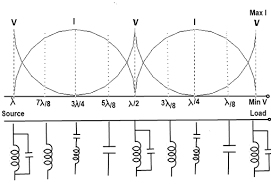
The bigger picture over a full wavelength: -

enter image description here

An open circuit t-line will look capacitive when very short and at a quarter wave will look like a short circuit. As length increases it looks inductive until at half a wavelength it looks like an open circuit again.

\$\endgroup\$
0
4
\$\begingroup\$

At the termination will get an inverting reflection that is proportional to the difference between the characteristic impedance and the actual termination. That will be inverted again by the 1/4 wave section to give a higher impedance at the input of the line.

The limit is of course if the line is shorted in which case you will get an infinite impedance at the input to the line - this is the usual 1/4 wave stub.

\$\endgroup\$
0
\$\begingroup\$

If you're already familiar with the Smith Chart, then it is the most intuitive way to look at what will happen in the situation described by your question.

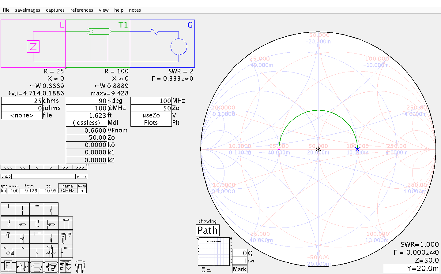
A \$\lambda/4\$ section of transmission line is equivalent to half a turn around the Smith Chart. If you terminate the line with a resistive load \$Z_L<Z_0\$ then the impedance \$Z_{in}\$ seen from the generator will always be \$Z_{in}>Z_0\$.

Look at the example in the pic below: a \$Z_L =25\ \Omega\$ resistive load transformed into \$Z_{in} =100\ \Omega\$ due to the quarter wavelength line section.

Smith chart quarter wavelength

\$\endgroup\$
0
\$\begingroup\$

Adding an answer to explain DC behaviour, which I suspect may be relevant for others who come across this question. For AC (RF) behaviour, Andy and Kevin have provided excellent answers.

When I measure the input terminals on that coaxial cable, what should I expect to see for an impedance? Would it be 50 Ω at that point, or should I expect to see a value > 50 Ω because of the way its terminated?

If by "When I measure the input terminals on that coaxial cable" you mean with an ohmmeter, which measures resistance (impedance at DC, 0 Hz), and the termination is purely resistive, then your ohmmeter will read the value of the termination (which you have specified is < 50 Ω). At DC, the resistance of the coaxial cable is negligible, assuming it's not very long. For instance, a Google search suggests that one kilometer of RG-58/U has a resistance of 32.81 Ω for the center conductor and 18.0455 Ω for the outer shield. So if you've got a 30 Ω resistive terminator at the end of a kilometer of cable, an ohmmeter would measure ~80 Ω at the other end.

If, however, you are measuring this with a network analyzer or other AC analysis (given that you mentioned you have a quarter wave length stub, I'm assuming you are), disregard. At DC, a quarter wavelength would be infinitely long, and therefore this measurement would be impractical.

\$\endgroup\$
2
  • 1
    \$\begingroup\$ I don't wish to pour anything nastly on your very reasonable answer but the question mentions a quarter wave section of coax cable and at DC, it has to be infinitely long. \$\endgroup\$
    – Andy aka
    Commented Apr 2, 2017 at 19:55
  • \$\begingroup\$ @Andyaka Of course, I just thought that others looking at this question might benefit from a DC analysis. I will clarify that a quarter wavelength at 0 Hz is very long. \$\endgroup\$
    – uint128_t
    Commented Apr 2, 2017 at 20:05
0
\$\begingroup\$

A too-low terminator will cause the cable to act as an inductive load on a signal driven into the cble.

A termination resistance that matches the characteristic resistance will not introduce frequency-selective loading due to the cable. That is equivalent to saying that the cable plus termination is resistive.

The use of a terminator of too-low resistance will (at low frequencies) cause a long cable and terminator to be inductive, i.e. will make a load on the driver that is equivalent to an inductor to ground. At high frequencies, there are also line-length interactions with the wavelengths of the driven signal.

\$\endgroup\$

Your Answer

By clicking “Post Your Answer”, you agree to our terms of service and acknowledge you have read our privacy policy.

Not the answer you're looking for? Browse other questions tagged or ask your own question.