0
\$\begingroup\$

So I've wired up a relatively simple circuit where an Arduino controls a solid state relay that is connected to a 12V 30A power supply which runs a solenoid valve. I'm using the an Arduino Mega 2560 a Gem Sensors solenoid valve and a Broadcom Limited ASSR-1511-001E solid state relay.

On the input side I have:

Arduino 5V --> SSR Pin 1 --> Out SSR Pin 2 --> 500 ohm resistor --> Arduino ground

And then on the load side I have:

Power supply positive terminal --> SSR Pin 6 (labeled as the positive pin) --> Out SSR Pin 5 --> Solenoid Valve --> Power supply negative terminal

So with that all in mind I find that when I power it all on it doesn't do anything. I've checked the voltage going through the input side and it is 5V on the dot but nothing on the load side. When I switch the connections on the load side it turns on and always stays on even with power turned off on the Arduino side and then my load side looks like:

Power supply negative terminal --> Solenoid Valve --> SSR Pin 6 (labeled as the positive pin) --> Out SSR Pin 5 --> Power supply negative terminal

Do you have any thoughts on what I'm doing incorrectly and what I can check to get this circuit running properly? I've got it prototyped on a perf board but it is pretty easy to switch everything around.

For some additional info:

  • The SSR input side has a max suggested amperage of 20mA. I have the 500ohm resistor on that line so at 5V (subtract the 1.65 voltage drop) that is 6.7mA on that line.
  • The SSR load side has a max of 2A and my solenoid valve has 20ohms of resistance so at 12V we're running around 0.5A.
\$\endgroup\$
20
  • 3
    \$\begingroup\$ How about drawing that as a schematic..... but it think your plus side on the output of the relay should be pin 6 and the negative side should be pin 4 \$\endgroup\$
    – Trevor_G
    Commented Apr 3, 2017 at 20:28
  • 1
    \$\begingroup\$ u mentioned way up there the voltage across 1, and 2 was 0V/.. sigh. Anyways.. tell me you have an appropriate fly-back diode across that valve coil. \$\endgroup\$
    – Trevor_G
    Commented Apr 4, 2017 at 2:19
  • 1
    \$\begingroup\$ @clifgray, see if you had added a schematic this whole question would have been a snap. YES you need a flyback across the coil of the solenoid. Otherwise the SSR fet will fry on the first turn off. \$\endgroup\$
    – Trevor_G
    Commented Apr 4, 2017 at 16:53
  • 1
    \$\begingroup\$ clifgray, the tragedy, the heartbreaking tragedy, here is that you should have presented a schematic and @Trevor and myself went with you not doing so...and it backfired on us. That's a day wasted. You've no idea how many of the regular (critics...sorry...users) users here would have beaten down on you and refused to talk until you had a schematic up. And how right they are (sigh) \$\endgroup\$
    – TonyM
    Commented Apr 4, 2017 at 18:47
  • 1
    \$\begingroup\$ Well that solved it and it is working correctly now. I'm just getting started in this area so I appreciate the now totally understood requirement for a schematic. Thanks for highlighting it. \$\endgroup\$
    – clifgray
    Commented Apr 4, 2017 at 19:28

2 Answers 2

1
\$\begingroup\$

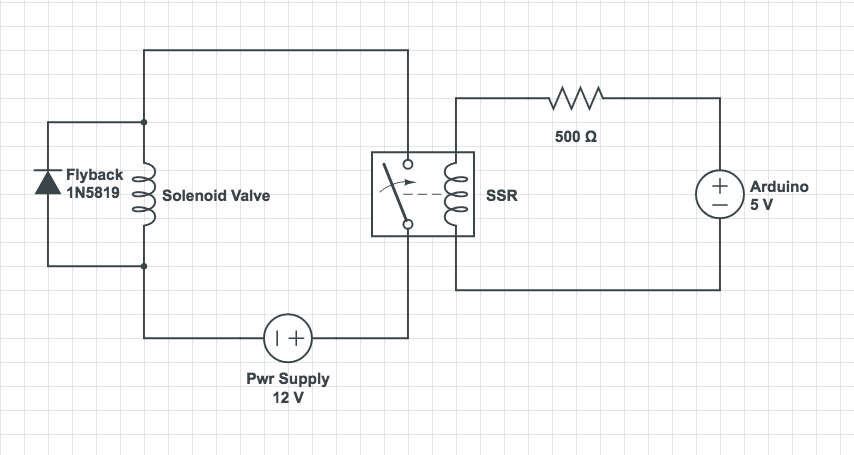
To make the solution clear in case anyone has this same issue, I was getting some kickback from the inductive load of the solenoid valve. I had been successfully running some 2W solenoid valves with this same solid state relay without issue but then with the larger Gem Sensors 6W valves it turned out that the inductive load was frying the SSR when I turned it off. I'm now running a 1N5819 Diode as a flyback diode to protect from that inductive kickback and the circuit is running just fine. I've included a schematic below, this is my first schematic so let me know if anything is unclear!

enter image description here

\$\endgroup\$
1
  • 1
    \$\begingroup\$ You drew the SSR backwards,,, but as I suspected, you needed a fly-back diode. \$\endgroup\$
    – Trevor_G
    Commented Apr 4, 2017 at 20:16
0
\$\begingroup\$

Generally a SSR is for AC only, not dc. Because DC never crosses 0 volts, the SCR can never turn off once energized.

A better DC switch would be a transistor or FET.

\$\endgroup\$
2
  • \$\begingroup\$ I was thinking that might be an issue but this one has in the documentation: "ASSR-1511 enables AC/DC and DC-only output connections. For DC-only connection, the output current, Io, increases to 2A and the on-resistance, R(ON) reduces to 0.2ohm." \$\endgroup\$
    – clifgray
    Commented Apr 3, 2017 at 21:54
  • \$\begingroup\$ DC SSRs are made from FETs, AC SSRs use triacs. It's pretty poor to not even look at the datasheet before writing an answer, which clearly shows all this. \$\endgroup\$
    – TonyM
    Commented Apr 4, 2017 at 8:07

Your Answer

By clicking “Post Your Answer”, you agree to our terms of service and acknowledge you have read our privacy policy.

Not the answer you're looking for? Browse other questions tagged or ask your own question.