0
\$\begingroup\$

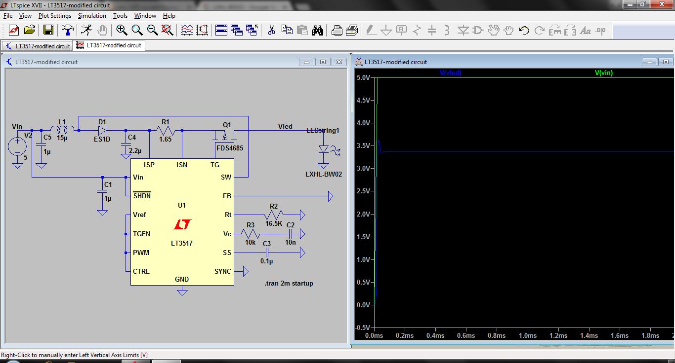
I am trying to build a boost converter using LT3517 with 5V input. LED and input voltage(5V) is constant for our application. I need to tune the circuit between this and the current across the LED should be 500mA as per our application. so I put 1.65 ohms current sense resistor.

But 5V input is not switching/boosting the voltage. can i know the reason for it?

what is the mistake i made in the below circuit? How can I boost myenter image description here voltage?
\$\endgroup\$
4
  • 1
    \$\begingroup\$ What is the rated forward voltage drop for the LED? \$\endgroup\$ Commented Apr 4, 2017 at 4:13
  • 1
    \$\begingroup\$ This does not appear to be a circuit recommended in datasheet. So where did you get the circuit? \$\endgroup\$ Commented Apr 4, 2017 at 4:33
  • \$\begingroup\$ This is the demo circuit which I downloaded in LT. \$\endgroup\$ Commented Apr 4, 2017 at 5:38
  • \$\begingroup\$ I also tried the circuit which is given in datasheet. but the voltage is not boosting it up. \$\endgroup\$ Commented Apr 4, 2017 at 5:39

2 Answers 2

2
\$\begingroup\$

I need to tune the circuit between this and the current across the LED should be 500mA as per our application. so I put 1.65 ohms current sense resistor.

The current through the LED is determined by the formula 100mV / Rsense

With Rsense at 1.65 ohms, the current limit is 61 mA, about ten times lower than what you calculated.

As per the other answer, you need to have the feedback pin appropriately connected. Be also aware that running at 5 volts may be a problem if your LED string length count is more than two or three. Read the data sheet.

\$\endgroup\$
2
\$\begingroup\$

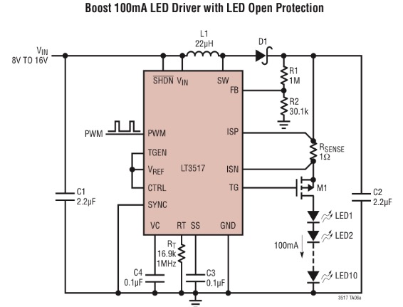
After a quick look I guess because you didn't follow the typical applications of the datasheet. The circuit you are showing here suggest you want to use the LT3517 as "Boost 100mA LED Driver with LED Open Protection". And that means you are missing the feedback resistor network R1/R2 on the FB pin. enter image description here

Try to add these or if you didn't add them on purpose tell us a bit more detail on what you are trying to do.

edit Looking at your comments and question again I realized that you might have another understanding problem. You are showing the VLed graph and claim that the voltage is not getting boosted. What you see here is the led voltage drop for the current you set with the current sense resistor. Check the current going through the Led and you should see a constant current through the Led that is getting regulated by the IT.

\$\endgroup\$

Your Answer

By clicking “Post Your Answer”, you agree to our terms of service and acknowledge you have read our privacy policy.

Not the answer you're looking for? Browse other questions tagged or ask your own question.