2
\$\begingroup\$

This is probably the most lame question of all the time here, but... I cannot understad grid-cathode "negative" polarization. For me, grid is always positive to the cathode. I mean, in practice, cathode is just GND or 0V, while grid gets voltage larger than zero and never goes below zero. So how come it has negative voltage comparing to cathode?

Let me show you how I understand a triode operating.

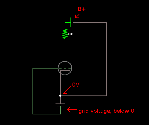
This is the most basic grid-cathode polarisation example and it does make some sense for me. We have reference 0V and this is cathode electron emitter, but we also have a battery connected below zero:

enter image description here

This example "seems legit" - cathode is connected to 0V but grid has own battery that provides voltage which is (theoretically) below zero*.

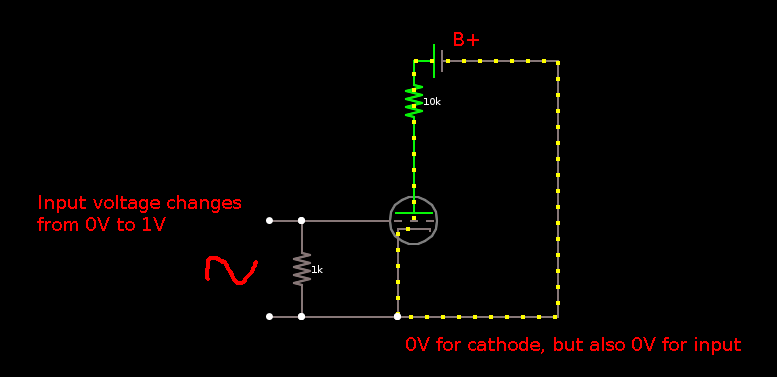
However, in real life no such battery exists, and there's just one 0V/GND point, common both for cathode and input signal.

What's more, the input voltage changes from 0 to 1V (not from -1V to 0V) in my example, so... how does the tube even work? It should not pass possitive voltages through the grid at all and the tube shouldn't work. But it does:

enter image description here

The resistor is of course the key, however it never drops input voltage BELOW 0V because there is no "below zero" point in the circuit. The ultimate zero is just zero, the same 0V point cathode emitts electrons from.

Or is it and I'm just unable to see it?

*) for me in this example grid voltage is stil positive over the cathode :/

\$\endgroup\$
5
  • \$\begingroup\$ Are you claiming that the first circuit is somehow working? Also have you measured in the first circuit that the node you claim to be 0V is really 0V? \$\endgroup\$
    – Envidia
    Commented Apr 5, 2017 at 23:59
  • 2
    \$\begingroup\$ "However, in real life no such battery exists" - are you kidding. Every battery can do this. Of course grid is taken negative to cathode - that is how anode current is controlled - go and read-up on triodes. \$\endgroup\$
    – Andy aka
    Commented Apr 6, 2017 at 7:54
  • \$\begingroup\$ The grid needs to be negative in order to control the flow of electrons between cathode and anode. Control is achieved by impeding the main electron flow to a greater or lesser extent according to the demands of the input signal voltage. \$\endgroup\$
    – Chu
    Commented Apr 6, 2017 at 15:00
  • 1
    \$\begingroup\$ Never seen a grid bias battery? \$\endgroup\$
    – user16324
    Commented Apr 6, 2017 at 19:38
  • \$\begingroup\$ @BrianDrummond I saw - in very first chapters of tubes-for-beginners books. Later always a resistor was used as a grid bias. \$\endgroup\$
    – emroe
    Commented Apr 6, 2017 at 19:56

5 Answers 5

4
\$\begingroup\$

There are several types of biasing in tube amplifiers. Your schematic shows one particular type, grid-leak biasing. Grid-leak biasing is by far the hardest to understand, and many erstwhile explanations expect you to push the "I Believe" button and go on. At first blush, it does seem magical: How can the grid get negative with respect to the cathode, there being no negative biasing voltage supply? It's even harder to understand if you were trained that current flows from positive to negative. It’s easier if you were military trained or your training is in physics (both of which acknowledge that current flow is negative to positive).

The key to understanding how grid-leaking biasing works is to dig deep into the physics of how a tube works. The heater heats the cathode. The cathode has a coating that, when heated, creates a cloud of electrons around it. Some of these electrons fall back into the cathode, some escape, and some bang into the nearby grid wire - not many, because, after all, nothing is attracting them (compared to plate B+). But there are some with high enough energy and direction to hit the grid wires and stay there. So now we have a grid with more electrons than it started with. If it were not for the resistor between grid and ground(cathode) the electrons would keep accumulating. But with this resistor the extra electrons have somewhere to go -- through the resistor and back to the cathode, so they are constantly bleeding off. Electrons flowing from the grid to the cathode (through the resistor) make the grid negative with respect to the cathode. Making the grid negative is biasing the tube.

Just a few, possibly helpful, comments...

  • Understanding how transistors work does not help you to understand how a tube works.
  • Thinking of a tube as a resistor network (e.g., the sum of currents into and out of a node equals zero, that kind of thing) also does not help here.
  • Thinking of how a thermocouple works DOES help, i.e. you get current flow without an external battery. Replace, in your mind, the cathode and grid with two dissimilar metals in contact (a thermocouple) and heat them. The process (though different) produces the same effect – a small current flow with no external voltage source.

I hope you find this explanation helpful.

\$\endgroup\$
1
  • \$\begingroup\$ The biasing model for a triode and the N-channel JFET are the same (albeit realised in a different way) so if one understands triode operation, JFET operation becomes intuitive. In that sense, understanding one helps to understand the other. \$\endgroup\$ Commented Apr 7, 2017 at 14:28
3
\$\begingroup\$

Triodes can work with positive grid voltages but are very rarely operated that way except in power amplifiers.

Grid current will flow when the input is positive which can cause distortion and if enough grid current flows the grid can heat to the point of causing damage. It is also not possible to reduce the anode current below the quiescent value using this approach

Tubes/Valves are in general designed to be operated with negative grid voltages.

Also triodes are most commonly used to amplify AC signals so the signal will not just go positive from the quiescent point but will go negative as well.

A common way to bias a triode is to include a resistor in the cathode such that the cathode current raises cathode by a few volts. The grid will be connected to 0v through a resistor so it has a negative voltage relative to the cathode. This is often called self-biasing.

Another way that is sometimes seen is to use a very high value grid resistor with the cathode connected to ground. The electron emission from the cathode will result in a small grid current that flows through the high-value grid resistor to give a volt or so negative bias on the grid. This is called grid-current biasing.

\$\endgroup\$
3
  • 1
    \$\begingroup\$ It's been a very long time for me. But the resistor involved in grid-current biasing was sometimes just called a grid leak resistor, memory serving. \$\endgroup\$
    – jonk
    Commented Apr 6, 2017 at 0:52
  • \$\begingroup\$ A long time for all of us, that terminology was around in the 1920's and 30's. \$\endgroup\$ Commented Apr 6, 2017 at 1:38
  • \$\begingroup\$ I guess I've just been dated. ;) \$\endgroup\$
    – jonk
    Commented Apr 6, 2017 at 3:53
2
\$\begingroup\$

I think, I understand why your triode works with a resistor in the place of a battery for a grid. A small amount of current flow in the grid and its potential becomes less than the cathode potential because of the resistor. The amount of current in the grid is so small that people assumes that it is null or call it 'gridleak'. Your resistor should be big to make it work..

\$\endgroup\$
1
\$\begingroup\$

Maybe it is just the question of what voltage means? According to Wikipedia the voltage is a measure of electric potential difference. A difference between two electric potentials. The question to ask is when a grid is said to be at negative potential, what is the reference?

The voltages showed on components’ data sheets are always expressed regarding a reference: the cathode. Tubes are no exceptions. Like @kevin-white said, adding a resistor in the cathode circuit would make the cathode to raise above grid potential reference. It is also possible to bias tubes with LEDs (voltage source).

auto bias tube

(See valve wizzard website).

In the schema you posted: 0 biased triode

The grid is at the same potential than the cathode hence Vgk = 0V. To create a negative Vgk, the cathode must be raised to a positive potential while the grid remains at the 0V reference (also called ground). To do so, a resistor is placed in the cathode circuit, the intensity that flows through the tube will also do in the resistor. Since U = R × I, the cathode will see its potential to raise above the 0V reference so Vgk becomes … negative. As it goes more and mores negative the tube, which is a conductance, will limit the current passing through it and an equilibrium is found depending on the value of the resistor.

There can also be a power supply that delivers a potential more negative than the 0V reference (negative power supply) used to polarize the grid.

\$\endgroup\$
3
  • \$\begingroup\$ You are right, I misunderstand "zero voltage" as literal 0V on battery clip. While it's not. However in your example it's easy to see the cathode is not directly connected to GND. But how about this one? Common-Cathode Amp What makes the grid "more negative" than cathode, if cathode is literally connected to GND, which is the most zero point in the circuit? \$\endgroup\$
    – emroe
    Commented Apr 6, 2017 at 19:53
  • \$\begingroup\$ I have augmented my answer. \$\endgroup\$
    – greg
    Commented Apr 7, 2017 at 9:27
  • 2
    \$\begingroup\$ @emroe In that circuit, the resistance between the grid and cathode is quite high. In this case the tube develops "grid leak bias" - essentially, some electrons that pass trough the grid on their way to the plate impact the grid and make it a bit negative. This way you can get a small negative voltage on the grid. If your circuit does not need this, then you use a smaller resistance between grid and cathode. \$\endgroup\$
    – Pentium100
    Commented Apr 7, 2017 at 9:43
0
\$\begingroup\$

You think that is confusing. If they had got it right about 300 years ago when they rubbed a sheet of glass and got a spark from it & assumed the electricity was jumping off, instead of electrons being rubbed off & jumping back on, electrons would be said to be positive & protons negative, & a positron would be a negatron. The anode of the valve would be negative & the grid positive. By the time they discovered they had muffed it (in the 19th century) it was too much trouble & too expensive to rewrite all the papers & republish all the books, so they still said current (conventional current) goes from positive to negative but electrons go from negative to positive. By the way, in maths the letter i (or J in electrical maths) represents √-1 ....no such number, but when you square it , it becomes -1. Sorry about that. I just couldn't resist!

Now I've thoroughly confused you, your second diagram is similar to a grid-leak biassing cct., but the resistor to ground is much higher (about 47K) & the input is fed through a capacitor. It is used for class C (fully ON-fully OFF) output stages in transmitters. When the drive signal goes positive, the grid conducts (picks up electrons), so the capacitor gets charged +||- . Then, as the signal heads towards zero & below, the capacitor provides negative bias, turning the valve off.

\$\endgroup\$

Your Answer

By clicking “Post Your Answer”, you agree to our terms of service and acknowledge you have read our privacy policy.

Not the answer you're looking for? Browse other questions tagged or ask your own question.