1
\$\begingroup\$

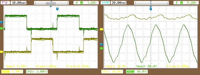
I want to use this Half Bridge Driver for a Buck converter Design. To validate it, I wire the connection as the simplified application diagram in the datasheet, with .1 uF capacitors. The input VDD is 12V. I feed the High and Low inputs with a %50 percent fixed duty cycle at a 15KHz frequency using a micro-controller as shown below on the Left. There was a small dead-band included for protection.

I expect the output at HO and LO without anything connected to be a square wave but I receive the output below on the right, where green is the low side, and yellow is the high side: enter image description here
What did I do wrong? What Can I check? When I turn the driver on without input I see a biased Voltage around 10V.

\$\endgroup\$
8
  • 1
    \$\begingroup\$ The high-side driver's bootstrapping needs the output FETs connected to be able to work properly. I'm guessing you didn't connect those ... ? \$\endgroup\$
    – brhans
    Commented Apr 6, 2017 at 20:25
  • \$\begingroup\$ SHOW. SCHEMATIC. \$\endgroup\$
    – winny
    Commented Apr 6, 2017 at 20:36
  • \$\begingroup\$ @brhans The MOSFETS need to be connected to see an output square wave? I'm using this for a synchronized buck converter. Do I also need to connect the inductor and capacitor? \$\endgroup\$
    – Nadim
    Commented Apr 6, 2017 at 20:37
  • \$\begingroup\$ @winny I have would added more pictures but I have limited posts authorizations. The connections are identical to the "Simplified Application Diagram" from the datasheet without the output connected. \$\endgroup\$
    – Nadim
    Commented Apr 6, 2017 at 20:42
  • \$\begingroup\$ Voltage is funny. What is 3.8V? \$\endgroup\$
    – user76844
    Commented Apr 6, 2017 at 20:51

1 Answer 1

2
\$\begingroup\$

I expect the output at HO and LO without anything connected to be a square wave

Don't.

The MOSFETS need to be connected to see an output square wave? ... Do I also need to connect the inductor and capacitor?

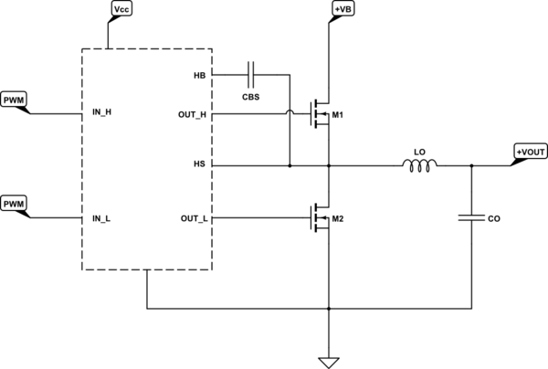
Of course! High side MOSFET needs a gate voltage higher than its source voltage to turn on. As can be seen from the schematic below, the voltage on its source is approximately the output voltage and CBS is used for "adding" this output voltage to the gate. That's called bootstrapping.

Here's how a bootstrapped driver is used in a sync-buck converter:

schematic

simulate this circuit – Schematic created using CircuitLab

NOTE: I didn't show the external diode because UCC27201 has it internally.

\$\endgroup\$

Your Answer

By clicking “Post Your Answer”, you agree to our terms of service and acknowledge you have read our privacy policy.

Not the answer you're looking for? Browse other questions tagged or ask your own question.