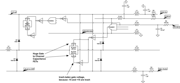
Multiplexers work well if:
1) you have the Load resistance (impedance) much higher than the Mux resistance; do not expect switch/channel resistance to match between ICs, and perhaps not between switches within the same IC; thus with Rmux of 100 ohms, varying 50 ohms, to have 0.1dB matching (1%matching) you need at least 5,000 ohms load and probably should be higher.
2) you keep the voltage being switched near the middle of the MUX's VDD range; if +5 and -5 VDD (two supplies) then you should get good (low distortion) near GND, if the Load is very high.
3) the MUX control lines will inject trash into the signals being switched, because the MUX uses big FET transistors to achieve low resistance switching. Those big FETs have wide channels and thus large gates and thus large Capacitance from Gate to Channel (through which you signal electronics flow); thus you must use R+C low pass filters on the Select wires, to exclude MCU trash or just RFI pickup.
4) The MUXes have finite frequency response, unlike a metal-switch-contact where the wiring inductance is the limit; this MUX F3dB (-3dB) comes from the MUX resistance and the Mux capacitance; usual specs on frequency response are done in 50_ohm environment, with popular spec being "10MHz with 50_ohm load"; you can expect 1,000X lower response (10KHz) if you raise the load to 50K ohms.
5) any VDD trash (such as on +5 and -5 rails, or +15 and -15 rails) will end up on the LARGE analog-mux-FET gates, and thus inject charge into the FET channels, which is your signal_path. Assume 10pF capacitance from your VDD rails into the signal_path.
How severe is this? assume 0.5 volt ringing at 1MHz from a switching power supply. The impedance of 1pF at 1GigaHertz is -j159 ohms. The impedance of 10pF at 1MHz is (down 10X to 16 ohms, up 1,000X to 16,000 ohms) 16,000 ohms.
If your load on the analog-mux is also 16,000 ohms, then you'll have 0.5/2 = 0.25 volts at 1MHz that ALSO comes thru/from that innocent analog MUX. Solution? lotta VDD filtering.

simulate this circuit – Schematic created using CircuitLab


