2
\$\begingroup\$

I have an idea to drive induction motors in a new way. I call it Variable Torque Drive (VTD). You are all familiar with VFD which utilize variable frequency and try to keep the torque constant. This method is vice versa. Let me explain.

sch 1

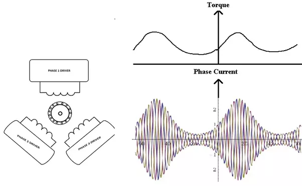
Assume I have this weird delta configuration to drive phase coils. Keep in mind that I can control the drive currents RMS amplitude like in the figure, on right. For some reason I can not change the frequency, but I have full control over the amplitude. You are seing the waveform of each phase currents in the figure. As you know IF you increase the phase currents you increase the torque.

Now lets assume I have a constant frequency at 100 Hz and I can deliver 0 to 100 Amps RMS currents. Please try to put aside what you already know about classical driving methods. Like I said, I have full control over the amplitude and If I don't allow current flow on field coilds, no currents will flow.

So since I can drive field coils at 100 Hz, its synchronous speed is 100*60 = 6000 RPM max. Now lets say I want to drive a loaded motor in 10 rad/s. Load is 10 KN and I can deliver up to 20 KN to the load. I also have speed sensors in on the rotor side. First I will deliver 15 KN to the load, and when I reach some speed close to 10 rad/s, I decrease delivered power to 5KN, then after the speed decreased down to some level below 10 rad/s, then I increase it to 12 KN, then 8 KN and it goes and on like this till I adequately regulate the speed at 10 rad/s. See the figure below to understand it better.

sch 2

The question is, since my synchronous speed is 6000 RPM, can I drive an induction motor with this method and control the speed 0 to 5880 RPM(I figured the slip may be 2%). If so, does such method exist? If not, please explain why. Thanks.

\$\endgroup\$
12
  • \$\begingroup\$ This is the method used before VFD was available. It's not feasible because controlling the amplitude requires dumping huge amounts if heat. It also only works with asynchronous drives. \$\endgroup\$
    – Christian
    Commented Apr 20, 2017 at 10:42
  • 1
    \$\begingroup\$ 10 kelvin-newton load? \$\endgroup\$
    – winny
    Commented Apr 20, 2017 at 10:55
  • 2
    \$\begingroup\$ @Alper91 how do you control the amplitude? You said you don't want to talk about it, but it's the core of the problem. \$\endgroup\$
    – Christian
    Commented Apr 20, 2017 at 11:14
  • 1
    \$\begingroup\$ Ok. In that case I've nothing more to add which might be of use to you. \$\endgroup\$
    – Christian
    Commented Apr 20, 2017 at 12:11
  • 1
    \$\begingroup\$ @Alper91 Interesting stuff .You vary the amplitude and not the frequency .Well you still need some sort of inverter .You have shown this but if you do constant Frequency does that save pennies ? At low speed the way folk will understand this is they will think that it is not frugal on the battery.Do you somehow suck the power out of the rotor via the invertor .Is this your reason for using the triple bridge invertor which is not easy on the sporren ?I am watching your post and praying that it does not get downvoted .Have you measured the efficiency of your motor drive ? \$\endgroup\$
    – Autistic
    Commented Apr 20, 2017 at 12:39

2 Answers 2

3
+25
\$\begingroup\$

In the last 25 years there has been an enormous amount of evolution and technology that has gone into controlling 3 phase Variable Frequency Drives. Discussing any details around how to do it in a new method or better exceeds the scope of a forum such as this, but would be a good basis for a PHD thesis.

A good starting point in your study is Vector mode control, which is typically one of 3 standards modes to run an off the shelf VFD drive in.

Constant Torque is a standard mode in most VFDs - BUT if you are talking a 50 or 60 hz motor - why would you choose to run at 100 hz UNLESS you had a reduction in torque requirement in your 60 hz - 100 hz range. In my experience every 3 phase motor rated at a base speed of 60 hz has a reduction in torque capability for speeds above 60 hz.

You will also want to do some reading and study the Pull up torque curve which has been a staple in motor theory and motor manuals for 75 years. If you get a good grasp for how Vector control modes manipulate this Torque curve at various speeds - you will have a foundation to start with.

enter image description here

\$\endgroup\$
2
  • 1
    \$\begingroup\$ Thanks for the answer. But I sense that you imply this is not going to work. I actually think I grasped the vector control method and I can see that in FOC, inverter takes a response regarding to change in the slip. It does that via both controlling the frequency and amplitude, but in FOC, amplitude control is very limited while frequency control has wide range. I have a common response from everybody that even this method works it will fail thermally. I want to understand why? It seems the only obstacle in the method is thermal management. And I still didn't get it. \$\endgroup\$
    – Alper91
    Commented Apr 23, 2017 at 8:55
  • \$\begingroup\$ I'm not addressing the thermal heat issue. I'm questioning your ability to get a significant amount of constant torque at speeds greater than 60 hz. I have set up large horse power motors to run in the 60 to 80hz range and these applications always start with the understanding that speeds in those ranges require less torque than the motor is rated for. Can you do a test to graph the torque capability in the speed ranges above 60 hz? If the torque in the graph drops off at 60 to 100hz your mode wouldn't be constant torque. \$\endgroup\$
    – Tinkerer
    Commented Apr 23, 2017 at 19:32
6
\$\begingroup\$

The speed of an induction motor can only be controlled by changing the synchronous speed by changing the frequency of the supplied power or by changing the motor slip. The method that you have described is a means of changing the motor slip. The majority of the heat produced in an induction motor is heat produced in the rotor due to slip. The heat produced in the rotor is the slip percentage multiplied by the power transferred from the stator to the rotor. That is the reason that controlling the speed using that method has only limited use, primarily for controlling the speed of small fans.

This is illustrated and explained in my answer to: This Question

\$\endgroup\$
4
  • 1
    \$\begingroup\$ Thank you for the answer. But to increase the slip I also have to decrease the torque so phase current, so the power transfer to the rotor. Doesn't it compansate the heat dump? \$\endgroup\$
    – Alper91
    Commented Apr 20, 2017 at 11:31
  • 2
    \$\begingroup\$ See link added to my answer. It is a matter of how much power the load requires. \$\endgroup\$
    – user80875
    Commented Apr 20, 2017 at 11:42
  • 1
    \$\begingroup\$ @ charles cowie If it is for a car you need good low down torque unless you want to have a clutch to slip .Otherwise the car would not pull the skin off a three day old rice pudding .Are we all the pharesies and are we missing something ? \$\endgroup\$
    – Autistic
    Commented Apr 20, 2017 at 12:45
  • 1
    \$\begingroup\$ @Autistic Yes. Controlling induction motors by increasing slip is not good for any load that requires low-speed torque. The only such loads are fans and centrifugal pumps. \$\endgroup\$
    – user80875
    Commented Apr 20, 2017 at 13:00

Your Answer

By clicking “Post Your Answer”, you agree to our terms of service and acknowledge you have read our privacy policy.

Not the answer you're looking for? Browse other questions tagged or ask your own question.