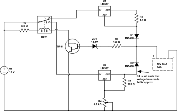
I have thought of making a smart lead acid battery charger using the following schematic. I am not sure if the circuit will work the way I expect it to, or not.
My expectations are:
- The battery starts charging at constant current mode through UI, as the relay's NC connects input to U1.
- When the closed circuit battery voltage crosses 14.1V (or a little more,) Zener breakdown happens in ZD1 and transistor TIP31 starts conducting. The relay turns on and now U2 starts getting input instead of U1.
- Now the battery charges at constant float voltage of approximately 14.2V (considering forward voltage drop at D2, the R4 is set in such a way that the output of the voltage regulating part is little higher than 14.2V, e.g. 14.5V.)
- I don't want to keep the charger always connected to the battery. So, when fully charged, I would disconnect the charger manually. This means I don't want the charger to make any extra effort to start or stop charging automatically.
The voltage values might slightly vary, I know. But, will the following circuit fulfill the expectation? Will this circuit fulfill these expectations? I am also in real doubt if I am going in the right direction to charge an SLA battery in 2 modes - first fixed current then fixed voltage. Please let me know if my expectation are right in order to make a working charger.

simulate this circuit – Schematic created using CircuitLab
