4
\$\begingroup\$

As part of a vintage radio restoration project, I decided to build a simple signal generator for alignment.

The idea was straightforward, a short distance AM transmitter with a variable carrier frequency in the MW band (at least 550kHz to 1.6MHz) modulated by a fixed low frequency audio tone (2kHz ). In my naivety, I decided to build the oscillators first: a JFET based Hartley for the carrier and a gain stabilized Wien bridge for the audio tone. So far, so good and both oscillators perform very well.

The JFET carrier oscillator is described here: What's the purpose of the diode at the JFET gate in this Hartley oscillator?

I thought the final step of modulating the audio tone would be simple. Boy, was I wrong. I have spent several days of trial and error with various (suitable) AM modulation schemes with very little to show. The montage below shows some of the modulators I've come across and I seem to be stumbling on the same issue with most of them: the band-pass filter! This makes sense, of course since most modulators are designed for transmission on a single carrier frequency. However, my requirement is that I can adjust the carrier across the broadcast band.

So, my question is this: how exactly do you design a modulation scheme for signal generator where the carrier frequency is adjustable?

Other notes:

One option I came across after I'd built the oscillators was explained (here). In this case the author varies the supply to the carrier oscillator itself which solves the problem of needing a second band pass filter as part of a separate modulator. However, I experimented with my JFET based Hartley and found that doing this led to a considerable amount of distortion (probably because the tuned circuit is at the JFET emitter).

I discovered that a major problem with many (all?) of these schemes is that even if you manage to get a half-decent AM output, when you adjust the carrier frequency you get large amplitude changes to the modulated output. It's almost like you'll need some kind of AGC control in place, even if you did manage to alter the band-pass filter in line with the carrier adjustment.

I considered using the second (smaller capacitance) section of my air variable tuning capacitor to form the band-pass that would change alongside the carrier frequency section. The result was a mess. It was too difficult to pick a suitable inductance to track the changing carrier. So, a good idea that proved difficult to achieve in practice.

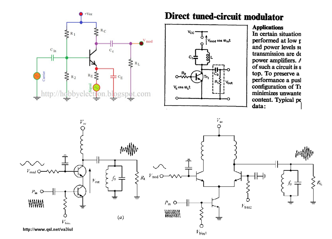
enter image description here

\$\endgroup\$

3 Answers 3

1
\$\begingroup\$

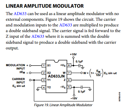
For these sort of low-ish carrier frequencies I'd consider using an analogue multiplier like an AD633. It has a small signal bandwidth of 1 MHz (3 dB down) so it will be maybe 6 dB down at 1.6 MHz. That is easily compensated for and you will get the benefits of a decent fairly linear modulation. Don't forget to add a DC offset to keep the modulation depth less than 100%.

enter image description here

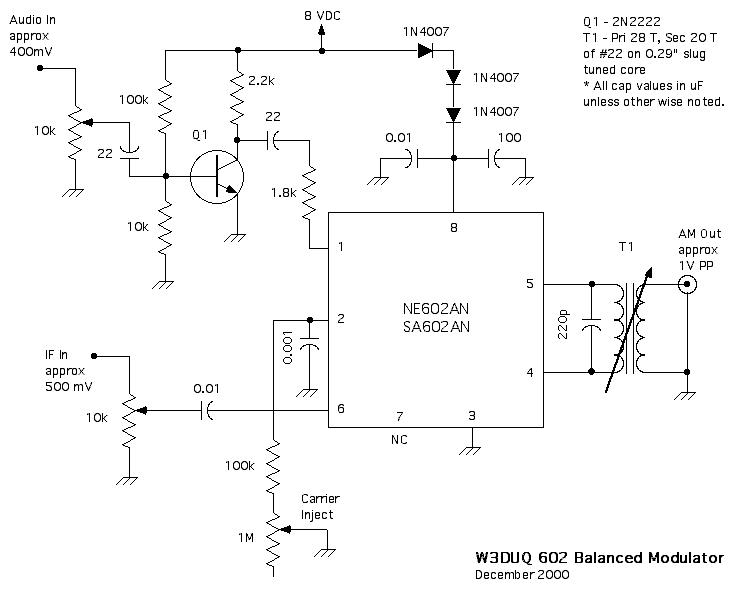
There is also the SA602: -

enter image description here

I would use the SA602A because it has a stabler temperature response and the SA602 may be hard to get hold of. It's good for well over 10 MHz from memory.

\$\endgroup\$
4
  • \$\begingroup\$ I was hoping someone would suggest an appropriate IC. I've focused on discrete solutions so far because I have them available. \$\endgroup\$
    – Buck8pe
    Commented Apr 24, 2017 at 12:21
  • \$\begingroup\$ Looking at the schematic, is T1 going to pose an issue similar to my earlier problems re carrier variation? I'll look at the datasheets in any event. Ta. \$\endgroup\$
    – Buck8pe
    Commented Apr 24, 2017 at 12:54
  • \$\begingroup\$ You don't need to use T1 - it's there to convert a balanced output to a single ended output. You can use either pin 4 or pin 5 as a single ended output. \$\endgroup\$
    – Andy aka
    Commented Apr 24, 2017 at 13:09
  • \$\begingroup\$ I had meant to get back to this sooner. I ended up using a 602 and a circuit not unlike the one you suggested. Worked like a charm! \$\endgroup\$
    – Buck8pe
    Commented Jul 30, 2017 at 14:09
4
\$\begingroup\$

You are trying to build a AM modulator "for alignment". That apparently means the carrier frequency needs to well known and controlled.

I would use a crystal and digital circuitry to generate the carrier frequency. You can divide a crystal down to something like 10 kHz, then a PLL to multiply that to whatever frequency you want. 10 kHz is plenty good enough resolution for aligning and calibrating AM radios.

Since this transmitter will be very low power and presumably used where it won't cause interference with other equipment, you don't have to worry about harmonics much. A amplitude-modulated square wave is much easier to produce than a amplitude-modulated sine wave kept clean of harmonics.

Amplitude modulating a square wave is as simple as clipping the tops to a varying supply voltage. The result will contain significant signal at the first few odd harmonics, but those will be well out of the band of the radio you are calibrating. A little R-C low pass filtering after the modulated square wave can cut down on those a bit quite easily.

So don't worry about resonant filters and the like, since those have to be tuned to your particular carrier frequency. All you have to do is change the divider in the PLL to set the multiple of 10 kHz you want your carrier frequency to be.

\$\endgroup\$
3
  • \$\begingroup\$ As an SDR person, I like your approach. \$\endgroup\$ Commented Apr 24, 2017 at 12:24
  • \$\begingroup\$ I like this idea a lot. If I have to abandon my current approach (which is likely), I'll probably follow this path. \$\endgroup\$
    – Buck8pe
    Commented Apr 24, 2017 at 12:47
  • \$\begingroup\$ If you don't need a great resolution, a simple PWM based approach with a Microcontroller playing the role (or rather, including) of both the oscillator as well as the PLL would do – you can typically run PWM units at frequencies beyond 40 MHz, and by changing the overall accumulator width of a 50% duty cycle PWM, you can generate a fixed set of frequencies. \$\endgroup\$ Commented Apr 24, 2017 at 12:52
1
\$\begingroup\$

The classical mixer problem (I call it classical. Noone else does.)

Let's first assume you're dealing with a perfect analog multiplier used as mixer:

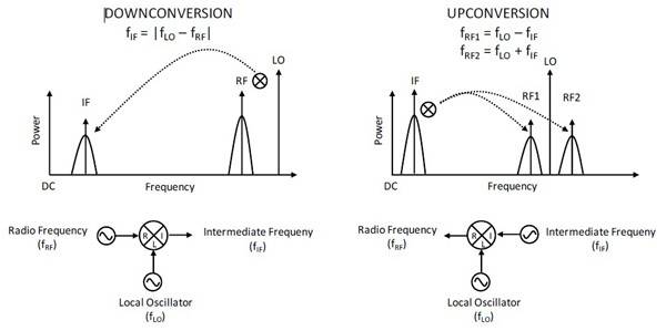
mixing principle
figure from here.

So, what multiplying two cosines does is the following:

$$\cos(x)\cos(y) = \frac12\left(\cos(x+y)+\cos(x-y)\right)$$

So, by multiplying your 20 kHz tone (\$x=2\pi 20\,\text{kHz}\$) with your let's say 1MHz (\$y=2\pi1000\,\text{kHz}\$) carrier, you actually get two cosines, one for the upper, one for the lower sideband, at 980 and 1020 kHz, respectively.

If your mixer isn't a perfect multiplier, you also get the 1 MHz fed through.

Now, the problem here is that your mixing LO spans a large range: from 550 kHz to 1600 kHz means that you can double him twice. Why's that a problem?

To produce the multiplying effect, all our mixers depend on the nonlinearity of some device. I'll abstract (and simplify) this a bit, because calculating the current gain of a transistor circuit is a bit out of scope, here.

The current that flows into the collector of a transistor is not a constant multiple of the current flowing into the base (we can only make that simplification for relatively small variations of the base current). Instead, it looks more like an exponential function.

Now, an exponential function \$e^t\$ can be represented by a series

$$\begin{align} e^{t} &= \sum_{n=0}^\infty \frac{t^n}{n!}\\ &= \frac{t^0}{0!} + \frac{t^1}{1!} + \frac{t^2}{2!} + \frac{t^3}{3!} +\frac{t^4}{4!} +\dots\\ &= \frac{1}{1} + \frac{t}{1} + \frac{t^2}{1\cdot2} + \frac{t^3}{1\cdot2\cdot3} +\frac{t^4}{1\cdot2\cdot3\cdot4} +\dots\\ &= 1+t + \frac{t^2}{2} + \frac{t^3}{6} + \frac{t^4}{24} +\dots\\ \end{align}$$

So, the first term, \$1\$, is uninteresting. It's just a DC offset to us.

The second term, \$t\$, just means we pass through the input.

The fourth and later terms are all attenuated by a factor of 6, 24, 120,… so let's say we'll consider them later.

The third term, \$\frac{t^2}2\$, now, gets interesting. Let's look at that!

What if our signal \$t\$ is a actually a sum of two signals, as above, \$t=x+y\$? Well, binomials to the rescue:

$$\begin{align} \frac 12 \cdot t^2 &= \frac 12 \cdot (x+y)^2\\ &= \frac12\left(x^2 + 2xy + y^2\right)\\ &= \frac12x^2 + \frac12 2xy+\frac12 y^2\\ &= xy + \frac12 x^2 + \frac12 y^2 \end{align}$$

See that \$xy\$ there! That's the multiplication we need. Awesome! It's also the "strongest component in that sum!".

Now, sadly, \$\frac 12 x^2\$ and \$\frac12 y^2\$ do not magically disappear.

if \$x= \cos(2\pi 550\,\text{kHz})\$, then that means we're also multiplying it with itself, and get 1.1 MHz :( Nothing we can do about that, so we'll have to filter it out.

Now, sadly, a filter that cuts out at 1.1 MHz can't be used to let through a 1.6 MHz AM signal! So, you'll need to switch filters somewhere. Filters aren't perfectly flat and identical, so there you get your amplitude variations.

A possible method of dealing with this here is using an intermediate step, an intermediate frequency (IF), to do your mixing.

Idea is this: Mix your 20 kHz up to a frequency of let's say 10 MHz (+- 20kHz). Now, mix it down with a 8.4 MHz to 9.5 MHz oscillator. The square products will be far out of your band of interest, and you can use one, much flatter filter.

\$\endgroup\$
3
  • \$\begingroup\$ Let me see if I get what you're saying, you're suggesting I produce a high frequency signal which I modulate (mix?) with my LF tone. Then I use a variable oscillator that's 500khz to 1.5MHz odd below this high frequency and I transmit the difference frequency. Is that the general idea? \$\endgroup\$
    – Buck8pe
    Commented Apr 24, 2017 at 12:40
  • \$\begingroup\$ I'm struggling to see how you extract the difference frequency. Can you expand a little on the last paragraph? It sounds like a good idea (sort of like the LO in a superhet radio), but I'm struggling with the detail. \$\endgroup\$
    – Buck8pe
    Commented Apr 24, 2017 at 12:43
  • \$\begingroup\$ no, that's not the idea :) You modulate a 10 MHz carrier, and then mix it down by 9.5 MHz (10 MHz - 9.5 MHz = 500 kHz) to 8.4 (10 MHz-8.4 MHz = 1.6 MHz) to get the signal you want. It is a superhet, with the IF > RF :) You're absolutely on the right track. Whenever mixing, you get both the sum and the diff frequency, see my first formula :) \$\endgroup\$ Commented Apr 24, 2017 at 12:45

Your Answer

By clicking “Post Your Answer”, you agree to our terms of service and acknowledge you have read our privacy policy.

Not the answer you're looking for? Browse other questions tagged or ask your own question.