1
\$\begingroup\$

So, I am familiar with what a Gilbert cell is and what it does, but I have looked through all the resources I can find trying to understand it and I just can't wrap my head around it.

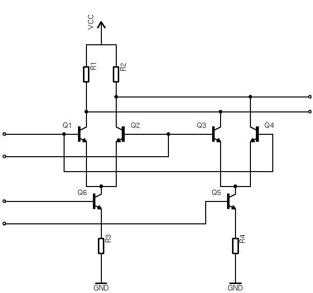
Gilbert cell schematic from Wikimedia Commons

Just from looking at it, I can tell it has something to do with differential amplifiers; it looks very much like a long-tailed pair of long-tailed pairs.

It could just be that my brain is fried from working on final projects and final exams, but I can't seem to understand it.

\$\endgroup\$
2
  • \$\begingroup\$ You are missing a connection between the emitters of Q5 and Q6 so that the inputs to to those transistors are differential. en.wikipedia.org/wiki/Gilbert_cell#/media/… \$\endgroup\$ Commented Apr 28, 2017 at 1:45
  • \$\begingroup\$ I thought that seemed weird. \$\endgroup\$
    – Hearth
    Commented Apr 28, 2017 at 1:51

3 Answers 3

1
\$\begingroup\$

it looks very much like a long-tailed pair of long-tailed pairs.

That's exactly what it is.

Q6 and R3 form a voltage controlled current sink, which allows a total current proportional to the voltage at the base of Q2 to flow through the long tailed pair Q1, Q2. Q5 and R4 do the same thing, with the voltage at the base of Q5 determining the total current through the second long-tailed pair Q3, Q4.

A balanced AC input to Q6base and Q5base will thus control the ratio of currents flowing trough the two upstream diff pairs: if the voltage difference between Q6base and Q5base is zero, the currents are equal. If Q6base is higher than Q5base, Q6 will sink more current than Q5, and vice versa. Keep in mind that the sum of the two currents is always the same, unless the input is overdriven.

Assume for now that the lower input is zero, and thus the total current is shared equally by the two long tailed pairs (Q1, Q2 and Q3, Q4). Note how the outputs of the two long tailed pairs are cross connected. Q1, Q2 will have an opposite effect on the output relative to Q3, Q4 for any nonzero signal to the bases of Q1/Q4 and Q2/Q3. As they are constantly "fighting" for control, they cancel each other out, leaving the output of the circuit at zero (differential) voltage.

The gain of a diff amp/long tailed pair is proportional to the common mode current flowing through it. Thus the lower input controls how much weight one diff amp has over the other: if the non-inverting pair has more current flowing through it than the inverting one, the gain of the Gilbert cell is positive, and vice versa.

\$\endgroup\$
1
  • \$\begingroup\$ Ah, excellent! This in combination with @Whit3rd's answer makes things make a lot more sense now. So the double long-tailed pair is being used to cancel low-order terms involving input A (by Whit3rd's notation), and that leaves only the nonlinear AB term and B² term. I'm not entirely clear on how the B² term cancels (the symmetry of the device w.r.t. swapping A and B is not obvious) but I can kind of get an inkling of it. \$\endgroup\$
    – Hearth
    Commented Apr 27, 2017 at 14:17
1
\$\begingroup\$

The six-transistor 'multiplier' (or modulator, or demodulator) circuit has continuous output dependent on two differential-mode input signals. Call the two inputs A (the Q5 and Q6 base voltages) and B (Q1 and Q2 bases). Then the differential output (Q1 and Q2 collectors) can be expressed (because it is a continuous, smooth function of the inputs) as $$Vout = C_{00} + C_{10} A + C_{01} B + C_{20} A^2 + C_{11} A B + C_{22} B^2 + ...$$ This is the Taylor series expansion, with higher order terms omitted. Note, by symmetry, $$C_{00}= C_{01} = C_{10} = C_{20} = C_{02} = 0$$ This means that the lowest-order nonvanishing term is the product A X B. So, for small signals (which allows us to ignore the higher terms), the circuit is an analog multiplier of the A and B signals.

\$\endgroup\$
1
  • \$\begingroup\$ This makes a bit more sense to me than the other answer, thank you. It still isn't completely clear, but I have some idea of what's going on here. \$\endgroup\$
    – Hearth
    Commented Apr 27, 2017 at 11:09
0
\$\begingroup\$

A Gilbert Cell (actually Barry Gilbert patiently explains is NOT his creation; he does claim the translinear multiplier cell, very similar) is the analog version of an Exclusive Or gate.

If you drive the 2 sets of left inputs with differential square waves, you will see the (differential) EXOR on the right hand outputs. Assuming you drew correctly.

The Gilbert Cell is a doubly-balanced mixer, suppressing the energy from the bottom signals (usually the RF) and suppressing the energy from the top signals (usually the square-wave oscillator); this suppression leaves just the (weak?) SUM and DIFFERENCE; in a receiver, these will be weak if the RF input is weak; suppressing the RF and LO makes downstream filtering easier. In a Transmitter, suppressing the RF and LO leaves the SUM and DIFFERENCE as before, but your frequency plans (to filter out all but what you wish to transmit) may become easier and cheaper to implement.

\$\endgroup\$
1
  • \$\begingroup\$ I'm afraid you've lost me. I'm looking for a bit more of an intuitive explanation. Could be that this would be intuitive to someone from a digital background, or someone from an RF background, but my background is mostly in power electronics, so I'm completely lost. \$\endgroup\$
    – Hearth
    Commented Apr 27, 2017 at 3:23

Your Answer

By clicking “Post Your Answer”, you agree to our terms of service and acknowledge you have read our privacy policy.

Not the answer you're looking for? Browse other questions tagged or ask your own question.