1
\$\begingroup\$

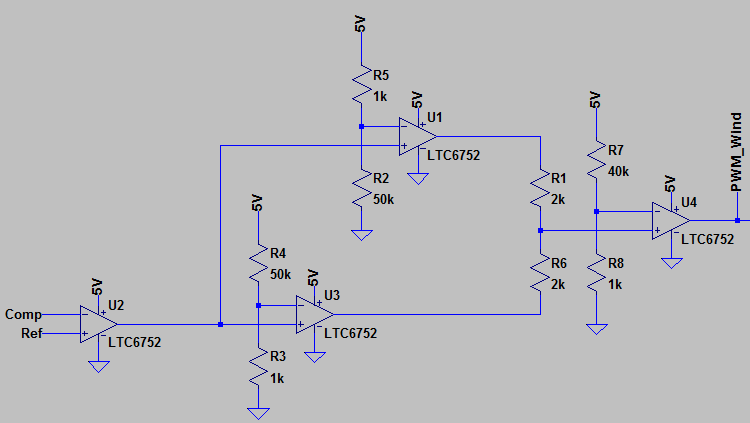
I'm trying to come up with a system which will reliably convert an arbitrary input to a PWM signal, and then back again. The comparison signal is a 50kHz sine wave, and the result is fed through a window comparator to reject any partial signals.

enter image description here

I've got the duty cycle conversion functioning perfectly, however I'm having difficulties demodulating the signal accurately.

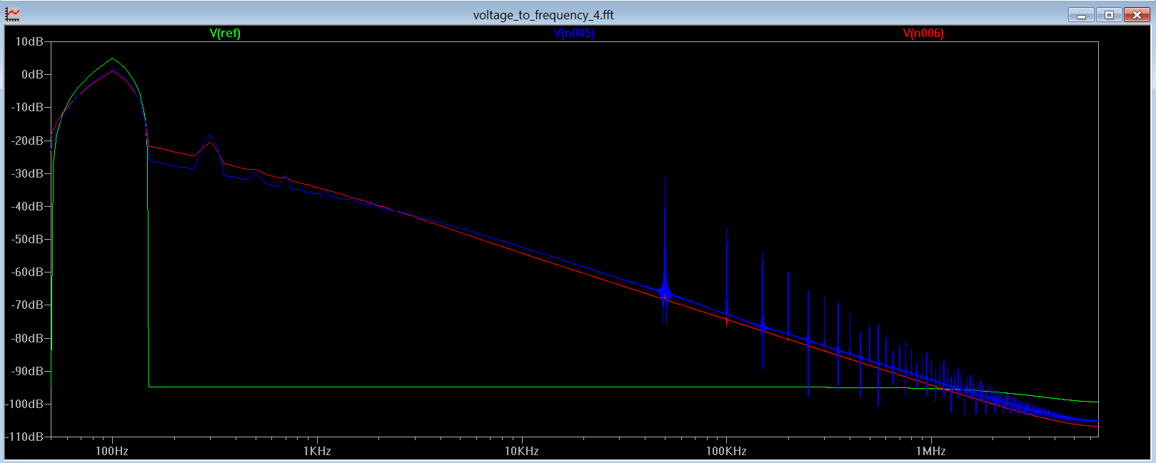
In the picture below the green trace is the input, the blue and red traces are from successive RC low pass filters.

Plots

There's a fair amount of distortion. Looking at the FFT it looks like it's being caused by other harmonics. FFT I'm wondering what I can do to produce a much more accurate output. I was hoping to have a fairly wide usable frequency range with this system. Adding more poles to the output just creates additional harmonics.
Thanks! EDIT: Result using a triangle as opposed to a sine wave, thanks to tomnexus. enter image description here

\$\endgroup\$
5
  • 3
    \$\begingroup\$ To make PWM you probably should compare to a triangle or sawtooth wave, not a sine wave. This would make the process nonlinear. Also, note that all distortion shows up as higher harmonics. The V against T plot is much more useful in diagnosing problems. \$\endgroup\$
    – tomnexus
    Commented May 2, 2017 at 5:26
  • \$\begingroup\$ Good point. I've made it a triangle wave. That made it substantially less awful. I've edited the result into my main question. So I guess the distortion was just caused because the sine wave it was comparing against has a variable rise/fall rate? The output pictured above has only a single pole filter. \$\endgroup\$ Commented May 2, 2017 at 5:53
  • \$\begingroup\$ Looks pretty good now - the only effect is the small phase delay of the filter. Ignore the first cycle or so, while the startup transient passes through the filter. \$\endgroup\$
    – tomnexus
    Commented May 2, 2017 at 6:04
  • \$\begingroup\$ Yeah, I can have a startup delay for the rest of the system. Thanks for the tip! \$\endgroup\$ Commented May 2, 2017 at 6:10
  • \$\begingroup\$ @tomnexus you might want to make that an answer, before someone comes along and eats your lunch. \$\endgroup\$
    – Neil_UK
    Commented May 2, 2017 at 7:10

1 Answer 1

1
\$\begingroup\$

To make PWM you probably should compare your (slow) incoming wave to a (much faster) triangle or sawtooth wave, not a sine wave. You need a waveform that has a a linear change in time_above_threshold with height_of_threshold. A sine wave makes the process nonlinear.

Your second graph shows this working well - just a small phase shift visible from the RC filter. You can ignore the first cycle or two, when the filters are getting over the startup transient of the simulation...

Note that all forms of distortion show up as higher harmonics. What you can't see in the FFT view is whether the waveform is becoming more square, or more sharp, or something else. (The detail is hidden in the phase of the higher harmonics, very hard to read by eye. An oscilloscope graph of V against time is much more useful in diagnosing problems with linearity.

\$\endgroup\$

Your Answer

By clicking “Post Your Answer”, you agree to our terms of service and acknowledge you have read our privacy policy.

Not the answer you're looking for? Browse other questions tagged or ask your own question.