I am learning different voltage to current converters during my bachelor thesis which are a composition of OpAmps and Transitors. The following structure is quite interesting for my thesis and I want to learn it by heart.
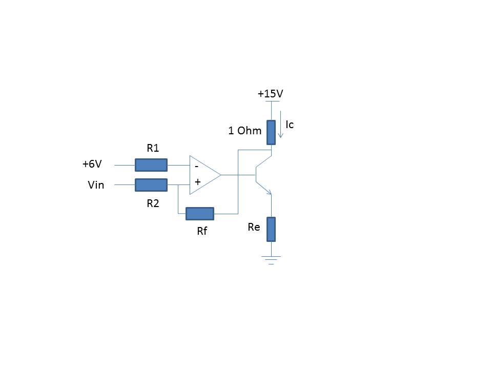
In this topology, I can see that if feedback is taken from Emitter to Inverting terminal of OpAmp (with +6V grounded), the output current seems quite stable in simulation and control seems very simple and also that the output voltage of OpAmp is Vbe higher the input voltage in case Rf = R1 (I would appreciate if i would know the disadvantages of that structure).
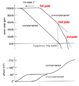
However, in case if feedback is picked from collector of transistor, as is shown here, the output current Ic is not stable anymore and there is continuous swinging on output current. I can't understand why does this happen. This was already discussed in What does this op amp/transistor circuit do? (revised circuit) from Andy Aka, according to him it happens because of OpAmp gain coupling with Collector gain of transistor which causes it to swings. I need more analysis in this direction- and will be very grateful if someone can suggest any literature on this swinging effect where I can learn it into details !
Secondly, the other problem with this topology is that if my emitter resistance is not constant and is rather a value within a given range calculated for this design, I can't directly calculate the output voltage of OpAmp as compared to former case wehre output voltage is simply input voltage plus Vbe. Is there any other way to calculate output voltage of OpAmp (Base voltage of Transistor) without knowing exact emitter resistance ?

Thanks alot for your answers !

