4
\$\begingroup\$

I've seen a lot on LEDs and series vs parallel resistor usage, but found nothing regarding the combination of both, so here goes.

I am working on a watch of sorts, that will work similar to a 7-segment display, where different LEDs are lit simultaneously depending on the driver's output (sometimes 2, sometimes all 7), so I will use that as an example.

In order to conserve battery, I am looking to have a low brightness during "normal" operation, with a momentary high brightness option. Since this needs to be rather small to be wearable I am, of course, looking to minimize component count. Cost is relevant, but much less of a factor than attaining a small size that can be hand soldered.

It is widely understood that running parallel LEDs on a single resistor is not the best approach, and I have allowed for a resistor-per-LED arrangement in my design, but I would like to be able to bypass SOME of the resistance temporarily.

What I figured I could do is put the Resistor-LED series pairs in a parallel array that feeds to a single resistor with a bypass, as in this schematic:
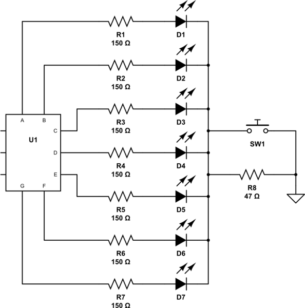
schematic

simulate this circuit – Schematic created using CircuitLab

So, the question: Would placing a single resistor in series with a parallel LED array be as bad if the LEDs also had dedicated series resistors, and if so, are there other alternatives for the dim/bright outcome I am looking for?

Additional Info
- I am planning on a 3v (2xAAA) battery source running LEDs with a Vf of 2-2.2.
- Once I have my LEDs, I intend on testing different resistance values for brightness yield, but am hoping for around 2-4 and 7-10 mA for the low & high respectively.
- The actual array will have 12 LEDs, with a maximum of 9 lit at one time.
- There will be 4 "digit" arrays in total.
- I am comfortable working with SOIC and 0805 (and some 0603) packages.
- If there is a risk of (slightly) uneven brightness from one LED to the next, that will be ok, as it will give a "battle worn" look that will work with the design.

\$\endgroup\$
4
  • 2
    \$\begingroup\$ I see no reason that wouldn't work. \$\endgroup\$
    – Hearth
    Commented May 6, 2017 at 3:03
  • \$\begingroup\$ Depending on your CMOS IC @3.3 it may have internal RdsOn equiv to 130 Ohms but ARM chips are 25 Ohms, so this must be included in calculations. Also 5mm 2V LEDs are about 10 Ohms ESR. Have you considered 3.7V LiPo cell instead? \$\endgroup\$
    – D.A.S.
    Commented May 6, 2017 at 4:23
  • \$\begingroup\$ @TonyStewart.EEsince'75 I was aware I have to consider the RdsOn of the MOSFET (would replace S1) in the total equation, but will also keep the CMOS in mind. Thanks for pointing this out. I am looking into alternative power sources, and will see what I can do with a LiPo. \$\endgroup\$
    – Jay
    Commented May 8, 2017 at 14:43
  • 1
    \$\begingroup\$ they make thin flexible LiPo cells for watchbands too with wire leads RdsOn of 74ALVCxxx is 25 ohms more or less , more (33 typ ohms) with 3.0V much less than 150 ohms \$\endgroup\$
    – D.A.S.
    Commented May 8, 2017 at 15:13

5 Answers 5

11
\$\begingroup\$

Your LEDs may or may not work exactly as you expect, depending on what you expect.

The change in brightness when operating the switch will vary depending on whether you have 1 or 9 LEDs lit. With 1 LED, the change will be small, with 9 LEDs, the change will be large.

With the switch closed, any number of LEDs will have the same brightness. With the switch open, as you turn on more LEDs, those already on will get less bright.

If you eliminate R8, and PWM the LEDs, you can achieve a constant brightness change regardless of the number of LEDs lit.

\$\endgroup\$
5
  • \$\begingroup\$ +1 for PWM, which is probably what OP needed all along. \$\endgroup\$
    – Mast
    Commented May 6, 2017 at 17:37
  • \$\begingroup\$ I think this is the way to go. Is there a way to (low side, I assume) PWM all of the LEDs with a single device/circuit? Either each of the 4 arrays, or all 4 combined would help with real estate. Thanks. \$\endgroup\$
    – Jay
    Commented May 8, 2017 at 15:06
  • \$\begingroup\$ I had the opportunity to confirm this through simulation and breadboarding, and it does exactly as I thought, but hoped it would not. Although not as dramatic, the presence of the series resistor R8 results in a change in brightness as the LEDs cycle through their differing on/off states. The fewer lit, the brighter. The more lit, the dimmer. One thing I would like to add is that the smaller R8 is in relation to Rs1-7, the less they are affected - but also, the less useful the idea becomes. PWM it is. \$\endgroup\$
    – Jay
    Commented May 11, 2017 at 19:44
  • \$\begingroup\$ Please do not PWM the LED's. I absolutely detest PWM display. They look so awful and cheap and are so distracting, especially if I am moving around and my eyes are darting back and forth. Maybe I am more sensitive than most people, I don't know, but I can't be the only one. \$\endgroup\$
    – user57037
    Commented Aug 12, 2017 at 17:59
  • 1
    \$\begingroup\$ @mkeith You're not the only one, I too have 'fast eyes', I can spot a VW car ahead at night (you will know what I mean, 95% of the population won't). Back in the slow CRT days, I would refuse to work at a desk, or alongside a colleague, with a monitor running at 60Hz, I became an expert in finding the relevant entries in the monitor driver, thank goodness for LCDs! We've lost the argument on PWM'ing LEDs, so I don't even bother to mention it these days. I recently built a charlieplexed display, at it was around 200Hz I finally got less uncomfortable with it. \$\endgroup\$
    – Neil_UK
    Commented Aug 14, 2017 at 6:35
5
\$\begingroup\$

A 3V battery is okay for red, orange yellow LEDs with lower forward voltages And not so well for white, blue and green. You might want to consider using a single rechargeable Lithium-ion cell which will increase the voltage to 3.6V. The discharge curve of a lithium cell remains above 3v until discharge cutoff.

Resistors do not work well for battery efficiency. The value of the current limiting resistor is chosen for a fixed voltage. As the battery voltage drops the efficiency will diminish, dimming the LEDs prematurely. The discharge curve of a AAA battery does not work well for LEDs that need to maintain their forward voltage.

A Constant Current Regulator (CCR) is the equivalent of a dynamic resistor that maintains the current irrespective of voltage.

The Microchip MIC2860 is a $0.25, 1mm x 2mm package, high efficiency LED driver which drives two LEDs at up to 30mA. This constant current regulator maintains the current with a dropout voltage of only 0.052 mV.

A resistor sets the maximum current, and the device will also optionally hold a brightness control value (32 levels) eliminating the need for a constant PWM dimming signal. When in standby the device draws only 0.01µA and will still hold the set brightness. It may also be controlled with PWM using the enable pin.

\$\endgroup\$
1
  • \$\begingroup\$ This sounds like a good direction to investigate for design changes. Thanks. I've read through the datasheet, but am still curious - can each array be driven by a single channel of the 2860 by just replacing R8, or MUST they be arranged 1 LED per channel and driven by Vin as in the datasheet example? For 4 arrays of 12, this would mean I need 24 chips (+required externals per) vs 2. \$\endgroup\$
    – Jay
    Commented May 8, 2017 at 14:36
2
\$\begingroup\$

Your LEDs will work exactly as you expect. The series resistor will limit the parallel strings to a maximum current of A/n where N is really set by the individual resistors. The two sections will balance each other out at some current that's highly dependent on the forward voltage and forward current of all the LEDs. The theoretical current through is somewhat difficult to calculate, and the practical results will vary based on the actual Vf vs. If of the LEDs and battery voltage, of course.

One LED, if you don't eyeball it properly, may be brighter than the others, and even if they look the same, the If and resistor tolerances may mean one is at 9 mA while another at 6 mA. I've put multiple identical LEDs in parallel with one resistor. One looked brighter than the rest. I simply replaced it with one that matched the brightness of the others. Longevity and current matching wasn't important to a one off project.

But it will essentially do what you think. Full brightness when the switch is pressed, shorting out R8, and some fraction of the brightness when R8 is in the way.

As for alternatives, a microcontroller with PWM control of the LEDs and a push button for input will provide finer control and many more options. Many microcontrollers work off 2x AAA just fine, so at most you are adding one SMD IC and maybe a bypass 0.1 µF capacitor. Code is better than discrete logic, IMHO. Imagine chasing LEDs or patterns on top of whatever Battle Worn look you think of.

\$\endgroup\$
1
  • 1
    \$\begingroup\$ Thanks for the input. I'm sure the µController would be more effective, but as of right now, I am trying to experiment and learn the roots of EE (discrete logic included), as an assumption that it will help me understand and control newer technology as I move forward. This is something I will be considering as my knowledge evolves. \$\endgroup\$
    – Jay
    Commented May 8, 2017 at 14:53
1
\$\begingroup\$

That's a fine design, partly because it forces you to get it right without the resistor in-circuit (i.e. in bright mode). Adding the resistor will simply lower the effective voltage to all the LEDs exactly the same.

Not every LED will respond the same way to that, so you may have unevenness in "dim" that you didn't have in "bright". That will only be a problem if the voltage-current curve of the LEDs are not the same.

\$\endgroup\$
0
\$\begingroup\$

If you could drive the LEDs from a SPI interface, the TLC5917 would solve your problem - and eliminate the series resistors. This device sets the current drive to all seven LEDs by a single resistor which could be switched to provide a change in brightness.

\$\endgroup\$

Your Answer

By clicking “Post Your Answer”, you agree to our terms of service and acknowledge you have read our privacy policy.

Not the answer you're looking for? Browse other questions tagged or ask your own question.