1
\$\begingroup\$

I was attempting the following problem. enter image description here
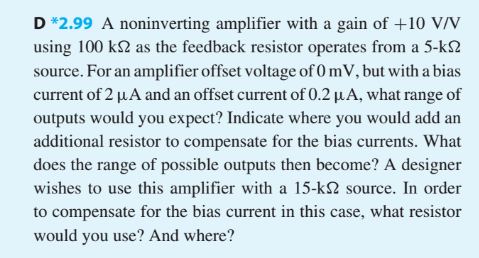
In the question it says there is a non inverting amplifier with a feedback resistor of 100k ohms and a source resistor of 5k ohms. If I use the regular non-inverting op amp formula for the gain I get 21 V/V as the answer.

But in the question itself it also says that the gain of the amplifier is 10 V/V. So which is it?

Also do they mean when they say that the gain is 10V/V, that the gain after removing the output voltage consumed by the input bias current and the off set current.

\$\endgroup\$
1
  • \$\begingroup\$ For a non-inv. configuration the source resistance has no influence on gain (ideal opamp properties assumed). It seems that the task requires you to select the second feedback resistor. \$\endgroup\$
    – LvW
    Commented May 8, 2017 at 16:39

2 Answers 2

2
\$\begingroup\$

The non inverting amplifier setup they are describing looks like this:

schematic

simulate this circuit – Schematic created using CircuitLab

You need to calculate the value of R3.

When they talk about "what range of outputs would you expect", they are talking about the output with V1 == 0V. That is not 100% clear in the problem description.

So given that, you should be able to calculate the output offset voltage from the bias and offset currents (assume different signs of the offset to get a range). The rest of the problem should be self-explanatory.

\$\endgroup\$
1
\$\begingroup\$

The question is not well written.

I think they mean that the amplifier is wired as a non-inverting amplifier with a feedback resistor of 100k.

Because of the bias current through the feedback network the actual output voltage will not be zero when the input is zero.

For example the 2uA bias current will cause 200mV to be dropped across 100K.

There will also be a voltage across the resistance of the source (5k) due to the input bias current.

It is your task to calculate the effect of the bias current given the input current and offset.

You are then asked how you would compensate for it.

The gain is taken as the slope of the output vs input so it ignores the offset voltages.

EDIT - removed reference to Thevenin equivalent resistance o feedback network. Although correct it is probably not what was meant.

\$\endgroup\$
3
  • \$\begingroup\$ I do not think, that the Thevenin equivalent is meant. For which purpose? This would make no sense at all. \$\endgroup\$
    – LvW
    Commented May 8, 2017 at 16:41
  • \$\begingroup\$ Oh I got it. When they say a source resistance of 5k, they do not mean the resistor on the inverting lead/wire. They mean 5k is the resistance of a source voltage attached to the non-inverting lead/wire. The resistance attached to the inverting lead can be calculated using the formula Vo/Vi=1+(R2/R1), where R1 is the unknown resistance on the inverting lead. The wording of this question is very terrible. \$\endgroup\$ Commented May 8, 2017 at 16:59
  • \$\begingroup\$ The Thevenin equivalent is the effective resistance that the bias current sees (that is the feedback resistance and the resistor to ground in parallel) However you're right in that you don't need it. The drop across the feedback resistor is independent of the resistor to ground. \$\endgroup\$ Commented May 8, 2017 at 17:01

Your Answer

By clicking “Post Your Answer”, you agree to our terms of service and acknowledge you have read our privacy policy.

Not the answer you're looking for? Browse other questions tagged or ask your own question.