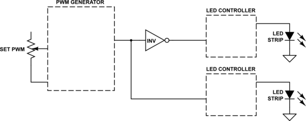
It sounds as though what you want is something to provide two different PWM signals to an LED power controller that accepts one, where one PWM signal is the inversion of the other one:

simulate this circuit – Schematic created using CircuitLab
The PWM generator can be anything you can find that is able to let you create a 0% to 100% PWM output at whatever control voltage you need. The "INV" device is just a properly compliant inverter. It could be a transistor of some kind or an actual logic gate (if it is compliant.) It's output will be the inverse of the PWM generator's output. In this way you get the exact opposite percent for one and the other inputs feeding into the two remaining devices: the LED controllers.
The LED brightness controllers need to be appropriate for your LED strip, or LEDs, or whatever you are using. And they need to accept a PWM input that they use to linearly regulate the percent of time they apply the set current to the LED lights.
Now, one more point to keep in mind. The human eye does not translate 50% duty cycle as 50% brightness. (Worse, there are two completely different "systems" in your eye: scoptic and photopic.) In broad strokes, brightness in your eye is a logarithmic thing. You can check out another link here at EESE for something to consider on that topic, too. You may want to use an audio taper or some way of arranging things with your PWM generator so that the light levels appear to be more linear as you adjust the control. But it's not necessary. Just a suggestion.


