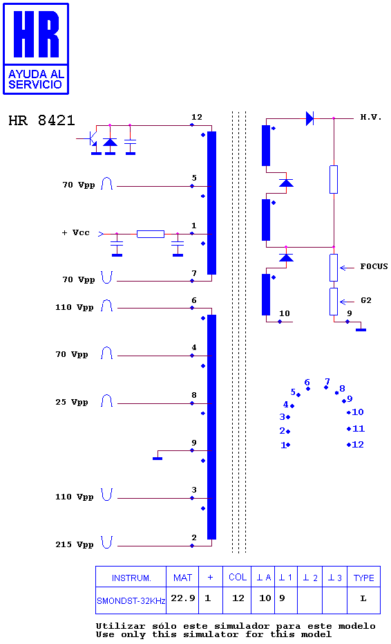
I am surprised that no-one has already asked this question (unless I've missed it), because it affects all those DIY guys dealing with high voltage. I have spent hours on the web to find how to use a CRT television flyback transformer to generate high voltage, and indeed, there are infinitely many schematics etc. on this subject: Basically, all the circuits I've seen use a supply somewhere between 12-30V DC, 3-5A, and they need an external wiring around the primary (not the internal primary coil). They almost never say if their circuit works with an internally rectified flyback (or not). Furthermore, these circuits are in general very inefficient (they dissipate a lot of heat). But that's not the point here. In CRT televisions, I know that the flyback works at 150V DC bias (what does it mean exactly?), in the rare cases where it is possible to find the spec of the flyback, it is very incomplete (e.g it says nothing about the inductances of the coils, the capacitance, the internal rectifiers). Even more annoying, I was unable to find any "real CRT television flyback" circuit that would have explained to me how they made the high voltage production efficient inside televisions. Well, I guess there are reference books on how to build a television, but even if I find them, it will probably be too hard a task for me to obtain these informations. To sum up my questions are:
How the 150V bias is used to improve the efficiency of the flyback (this question must probably be linked with the third question)
I know there are different kind of flyback topologies (resonant, quasi-resonant etc.). Is there a usual topology used in CRT television flyback (quasi-resonant?)
A schematic using the topology of your choice that explain only the high voltage production in CRT televisions (not the other features also related to the flyback like the electron beam deviation). To put bones on flesh, here is one of the most detailed flyback schematic I've found in the web. It can be used to answer the question, but that's not mandatory.

