0
\$\begingroup\$

I am practising for my radio license exam. One of the questions from an old exam:

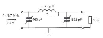
This filter belongs to a 3.7MHz transmitter. Approximate the impedance Z for a load of 50Ω.

enter image description here

Answers: 1kΩ; 50Ω; 10kΩ; or 10Ω.

I thought I could calculate the reactances of the inductors and capacitors (left is C1; assuming full values for the caps and 2.5uH for the inductor):

  • \$X_L = 2\cdot\pi\cdot3700000\cdot0.0000025 = 58.12\Omega\$
  • \$X_{C_1} = \frac1{2\cdot\pi\cdot3700000\cdot0.000000000463} = 92.90\Omega\$
  • \$X_{C_2} = \frac1{2\cdot\pi\cdot3700000\cdot0.000000001852} = 23.23\Omega\$

And then proceed to compute the substitution resistance of C2 with Rload (parallel), then combine with L (series) and finally with C1 (parallel). I do that with Pythagoras and get:

  • With C2 and Rload: \$Z_1 = \sqrt{50^2 + 23.23^2} = 55.13\Omega\$
  • With L: \$Z_2 = \sqrt{58.12^2 + 55.13^2} = 80.11\Omega\$
  • With C1: \$Z = \sqrt{92.90^2 + 80.11^2} = 122.67\Omega\$

This is not one of the answers. The correction model says it should be 1kΩ, but how should I calculate that?

\$\endgroup\$
6
  • 5
    \$\begingroup\$ Try using complex math rather than using simple magnitudes. \$\endgroup\$
    – glen_geek
    Commented May 23, 2017 at 14:23
  • \$\begingroup\$ @glen_geek OK, but how? Could you give me an example? \$\endgroup\$
    – user17592
    Commented May 23, 2017 at 14:29
  • 1
    \$\begingroup\$ I don't think a radio amateur exam will be looking for complex arithmetic. The reactance of C1 is \$\small 93\Omega\$ so the total impedance must be less than this (L/C2/R are in parallel with C1, so this lowers the overall impedance). Hence 1K and 10k are too high. L has a reactance of \$\small 80\Omega\$, and this will add to the series impedance of R/C2. Hence \$\small 93\Omega\$ in parallel with something greater the \$\small 80\Omega\$ will give about \$\small 50\Omega\$. 73! \$\endgroup\$
    – Chu
    Commented May 23, 2017 at 15:07
  • \$\begingroup\$ @Chu that makes sense, and indeed, the current answers seem more complicated than what I saw in the material so far. But, the answer model says it should be 1kΩ... I guess the correction model is wrong. Thanks & 73! \$\endgroup\$
    – user17592
    Commented May 23, 2017 at 15:16
  • \$\begingroup\$ Slight typo in first comment... I don't think a radio amateur exam will be looking for complex arithmetic. The reactance of C1 is \$\small 93\Omega\$ so the total impedance must be less than this (L/C2/R are in parallel with C1, so this lowers the overall impedance). Hence 1K and 10k are too high. L has a reactance of \$\small 58\Omega\$, and this will add to the series impedance of R/C2. Hence \$\small 93\Omega\$ in parallel with something greater the \$\small 58\Omega\$ will give about \$\small 50\Omega\$. 73! \$\endgroup\$
    – Chu
    Commented May 23, 2017 at 15:17

2 Answers 2

1
\$\begingroup\$

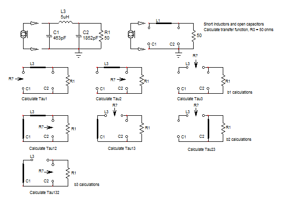
The Fast Analytical Circuits Techniques or FACTs will get you there without writing a single line of algebra, just draw little sketches that you can revisit in case you identify a mistake. First, we start with the network observed at \$s=0\$: open the caps and short the inductor. What remains seen from the input is the the 50-\$\Omega\$ resistance. We have \$R_0=50\;\Omega\$. Then, temporarily remove the energy-storing elements and determine the resistance "seen" from their connecting terminals. Here, for the natural time constants of the denominator, you reduce the excitation to 0 A or open-circuit the test generator used to determine the input impedance. You repeat the exercise as shown in the below figure:

enter image description here

You then assemble the time constants the following way:

\$D(s)=1+s(\tau_1+\tau_2+\tau_3)+s^2(\tau_1\tau_{12}+\tau_1\tau_{13}+\tau_2\tau_{23})+s^3\tau_1\tau_{12}\tau_{123}\$

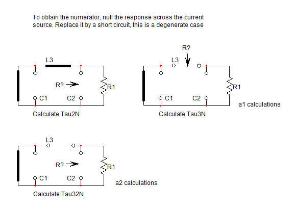
The zeros are found by nulling the response. Nulling means that the voltage across the current test generator to determine the input impedance is 0 V. 0 V across a current source is a degenerate case and you can replace the source by a short circuit. Again, "look" at the resistance offered in this mode by the energy-storing elements:

enter image description here

Once this is done, you can assemble the time constants to form the numerator \$N(s)\$:

\$N(s)=1+s(\tau_{2N}+\tau_{3N})+s^2(\tau_{3N}\tau_{32N})\$

The final expression for this input impedance appears in a low-entropy form and follows:

\$Z(s)=R_0\frac{N(s)}{D(s)}=R_0\frac{1+s\frac{L_3}{R_1}+s^2L_3C_2}{1+sR_1(C_1+C_2)+s^2L_3C_1+s^3(C_1C_2L_3R_1)}\$

You can further rearrange this expression in a nice canonical form as

\$Z(s)=R_0\frac{1+\frac{s}{\omega_{0N}Q_N}+(\frac{s}{\omega_{0N}})^2}{(1+\frac{s}{\omega_p})(1+\frac{s}{\omega_{0D}Q_D}+(\frac{s}{\omega_{0D}})^2)}\$

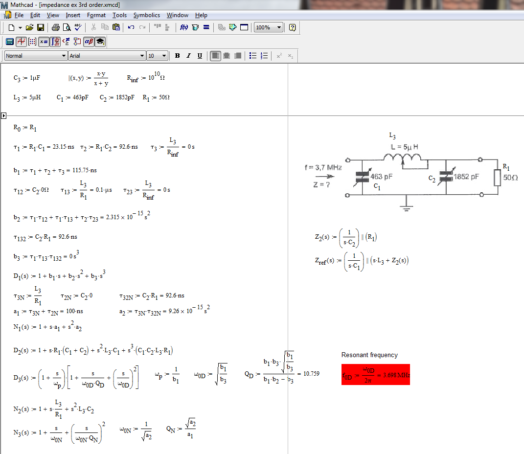
The below Mathcad sheet gathers all these equations for you and define all the terms needed in the above equation.

enter image description here

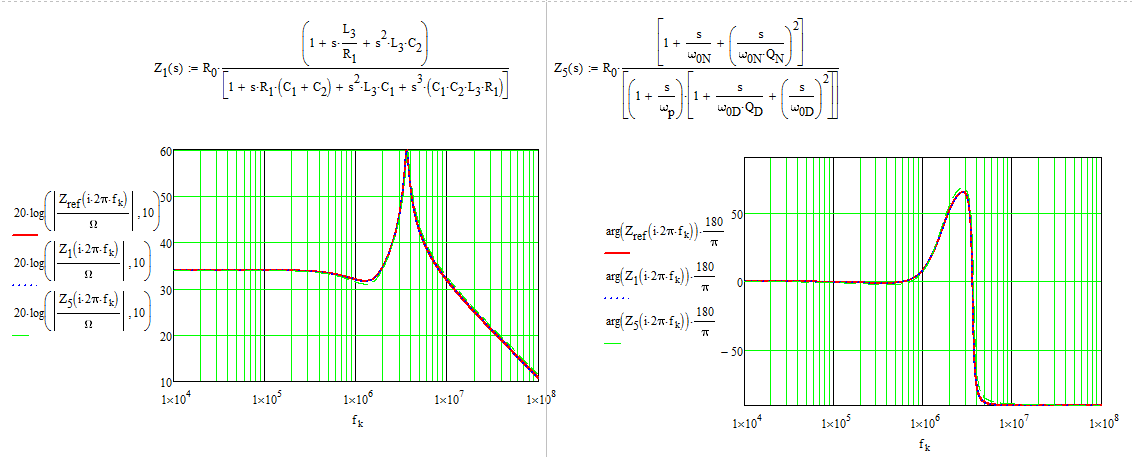
Finally, I plotted the raw expression (the simple paralleling of all the elements) and the two other expressions, the complete one and the canonical form. Not too bad! : )

enter image description here

You may be surprised by the approach here, with these FACTs. You have seen that I did not write a single line of algebra, just small sketches that I individually solved. The neat thing is that if I see a deviation between the raw transfer function and the one I derived, I can go back to the small sketches and solve the one which is wong. Try to do that with the brute-force expression : ) If you want to know more about the FACTs, you can check out this tutorial from APEC 2016 and also the list of transfer functions I derived in the book:

http://cbasso.pagesperso-orange.fr/Downloads/PPTs/Chris%20Basso%20APEC%20seminar%202016.pdf

http://cbasso.pagesperso-orange.fr/Downloads/Book/List%20of%20FACTs%20examples.pdf

\$\endgroup\$
3
  • \$\begingroup\$ Of course I forgot to mention the impedance at the resonant frequency: for a 3.698-MHz resonant frequency, the impedance with the given value is 925.2 ohms. \$\endgroup\$ Commented May 23, 2017 at 18:34
  • \$\begingroup\$ this approach is very interesting and new to me. I will look at the links you provided. Are you sure about the impedance, though? I get closer to 50 when using complex math....in fact, I get 68ohms! \$\endgroup\$
    – jrive
    Commented Nov 9, 2020 at 6:05
  • \$\begingroup\$ Yes, these FACTs are an amazingly powerful technique to deal with these types of structures. As you can see, I compare the FACTs response with that of the brute-force series-parallel arrangement and they are identical. For the sake of further verification, I run a quick SPICE sim and yes, the impedance peaks nearly 60 dBohms which is close to 1 kohms as indicated. Unless I used wrong components values in my sim and example? \$\endgroup\$ Commented Nov 9, 2020 at 7:05
0
\$\begingroup\$

One of the comments to your question mentioned performing the analysis using complex mathematics. Here is an outline:

The impedance of a resistor is R $$$$ The complex impedance of a capacitor is $$\frac{-j}{\omega \cdot C}$$

The complex impedance of an inductor is $$j \cdot \omega \cdot L$$

The definition of j is: $$j=\sqrt{-1}$$

Therefore: $$j\cdot j=-1$$

and: $$-j\cdot j=1$$

What you need, is to work out the impedance using your understanding of series and parallel connected components, substituting these impedance expressions. If you call the cap on the left C1 and the cap on the right C2, you will end up with the j terms which are complex numbers. It'll end up looking like:

$$\frac{\left( \frac{R \cdot \frac{-j}{\omega \cdot C_2}}{R+\frac{-j}{\omega \cdot C_2}} +( j \cdot \omega \cdot L)\right) \cdot \frac{-j}{\omega \cdot C_1}}{\frac{R \cdot \frac{-j}{\omega \cdot C_2}}{R+\frac{-j}{\omega \cdot C_2}} +( j \cdot \omega \cdot L)+\frac{-j}{\omega \cdot C_1}}$$

Expand the mathematic equation, multiply by the complex conjugate and take the square root. The complex expression z $$\frac{a+b\cdot j}{c - d\cdot j }$$

Has the conjugate z^* $$\frac{a-b\cdot j}{c + d\cdot j }$$

You flip the polarity of the j expressions from positive to negative or vice versa

Multiplying the two $$ Z \cdot Z^*=\frac{a+b\cdot j}{c - d\cdot j }\cdot \frac{a-b\cdot j}{c + d\cdot j }=\frac{a^2+b^2}{c^2+d^2}$$ Yeilds a real expression (not complex), but it is the square of the real magnitude, so you square root the answer

$$Z_j=\frac{\left( \frac{R \cdot \frac{-j}{\omega \cdot C_2}+( j \cdot \omega \cdot L)(R+\frac{-j}{\omega \cdot C_2})}{R+\frac{-j}{\omega \cdot C_2}}\right) \cdot \frac{-j}{\omega \cdot C_1}} {\left( \frac{R \cdot \frac{-j}{\omega \cdot C_2}+( j \cdot \omega \cdot L)(R+\frac{-j}{\omega \cdot C_2})}{R+\frac{-j}{\omega \cdot C_2}}\right) +\frac{-j}{\omega \cdot C_1}}$$

Multiply top and bottom of numerators and denominators by \$j\cdot \omega \cdot C_2\$

$$Z_j=\frac{\left( \frac{R +( j \cdot \omega \cdot L)(j \cdot R\cdot \omega \cdot C_2+1)}{j\cdot R \omega \cdot C_2 +1}\right) \cdot \frac{-j}{\omega \cdot C_1}} {\left( \frac{R +( j \cdot \omega \cdot L)(j \cdot R\cdot \omega \cdot C_2+1)}{j\cdot R \cdot \omega \cdot C_2 +1}\right) +\frac{-j}{\omega \cdot C_1}} =\frac{\left( \frac{R +( j \cdot \omega \cdot L)(j \cdot R\cdot \omega \cdot C_2+1)}{j\cdot R \omega \cdot C_2 +1}\right) \cdot \frac{-j}{\omega \cdot C_1}} {\left( \frac{R +( j \cdot \omega \cdot L)(j \cdot R\cdot \omega \cdot C_2+1)}{j\cdot R \cdot \omega \cdot C_2 +1}\right) +\frac{-j}{\omega \cdot C_1}}$$

$$Z_j=\frac{ \left( R \cdot (1 - \omega^2 \cdot C_2 \cdot L) + ( j \cdot \omega \cdot L) \right) \cdot -j } { \left( R\cdot (1 - \omega^2 \cdot C_2 \cdot L) + ( j \cdot \omega \cdot L) \right)(\omega \cdot C_1) + -j\cdot(j\cdot R \omega \cdot C_2 + 1)}$$

$$Z_j=\frac{ ( \omega \cdot L) -j \cdot R \cdot (1 - \omega^2 \cdot C_2 \cdot L) } { R\cdot (\omega \cdot C_1) \cdot (1 - \omega^2 \cdot C_2 \cdot L) + ( j \cdot \omega \cdot L) (\omega \cdot C_1) + \ R \cdot \omega \cdot C_2 + -j}$$

$$Z_j=\frac{ ( \omega \cdot L) -j \cdot R \cdot (1 - \omega^2 \cdot C_2 \cdot L) } { \left(R\cdot (\omega \cdot C_1) \cdot (1 - \omega^2 \cdot C_2 \cdot L) + R \cdot \omega \cdot C_2 \right)+ j\cdot \left((\omega \cdot L) (\omega \cdot C_1) -1\right)}$$

If my algebra works out... $$\vert Z \vert =\sqrt{\frac{ ( \omega \cdot L)^2 +\left(R \cdot (1 - \omega^2 \cdot C_2 \cdot L) \right)^2} { \left(R \cdot (\omega \cdot C_1) \cdot (1 - \omega^2 \cdot C_2 \cdot L) + R \cdot \omega \cdot C_2 \right)^2+ \left((\omega^2 \cdot L \cdot C_1) -1\right)^2}}$$

\$\endgroup\$
2
  • \$\begingroup\$ For the OP: the math is more tractable if one uses the numerical values from the start and computes the parallel and series values as Z = R + j X at each step. \$\endgroup\$ Commented May 23, 2017 at 23:21
  • \$\begingroup\$ Yes I agree, however a comment on the OP referred to complex mathematics which Keelan did not seem to be comfortable with. This analysis provides a primer which results in an equation which can be used to identify behaviour. It could be graphed for instance, on a 3d-plot, to show how the change in two variables result in a change in total impedance. Regards \$\endgroup\$
    – DWD
    Commented May 24, 2017 at 10:57

Your Answer

By clicking “Post Your Answer”, you agree to our terms of service and acknowledge you have read our privacy policy.