2
\$\begingroup\$

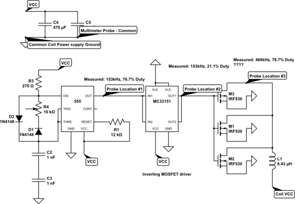
I used a 555 oscillator to drive a MOSFET array for my entry-level tesla coil setup. When I measure the frequency at the driver output (Location #2) everything seems normal. When I measure it at the MOSFET output (Location #3) I get an altogether different frequency. Why could that be? What improvements can I make to my circuit?

schematic

simulate this circuit – Schematic created using CircuitLab

Here's the circuit. the circuit

Thank you,

Riccardo

\$\endgroup\$
8
  • 3
    \$\begingroup\$ Please provide a more readable schematic and scope traces. You don't have a flywheel diode. Not only will the circuit not work well you may destroy the FETs. \$\endgroup\$ Commented May 26, 2017 at 20:15
  • \$\begingroup\$ @KevinWhite I cannot provide scope traces as I am using a multimeter to measure the frequencies and the schematic is the simplest I could make. I'll try improving it tomorrow if I can. Thank you for your interest in my question. \$\endgroup\$ Commented May 26, 2017 at 20:19
  • 4
    \$\begingroup\$ How is it "different". Higher? Your meter may be confused by ringing in the output, or just the high voltage. \$\endgroup\$
    – gbarry
    Commented May 26, 2017 at 20:53
  • 3
    \$\begingroup\$ Tying the MOSFET gates directly together is also a no-no. Small resistors to each device (a few ohms) helps with ringing. See "Rg" in the datasheet. \$\endgroup\$ Commented May 26, 2017 at 21:06
  • 5
    \$\begingroup\$ Seriously, you need an oscilloscope if you want to understand what's going on here. Hint: the waveform at point #3 is not entirely due to the MOSFETs. \$\endgroup\$
    – Dave Tweed
    Commented May 26, 2017 at 21:29

1 Answer 1

1
\$\begingroup\$

Since you do not show your scope traces, it is difficult to know exactly what you mean by "an altogether different frequency". Most likely, though, is that as Adam Lawrence suggests, you are getting ringing on the load. Multimeter frequency measurement for anything other than simple sine waves is a dangerous business, and I suspect that your meter is doing a bad job.

Instead of using the meter, do two things. First, drop your switching frequency way down, to something like 100 Hz. Now hook your scope to location 1 and location 3, and display both channels simultaneously. You should see a pulse train at location 1, and a sort of similar trace at location 3. Location 3 should have a more-or-less pulse train, except that, when the voltage goes high you should see a rather high-voltage damped sine wave. And note that the voltage can be well above the rating of your FETs, which is why you should listen to Kevin White and install a flyback diode across your load.

EDIT - As Dave Tweed pointed out, I missed the fact that you're trying to excite a Tesla coil. This makes life a bit more difficult. The above procedure will allow you to see why the output doesn't look like the input, but it won't drive the coil successfully. END EDIT
\$\endgroup\$
2
  • 1
    \$\begingroup\$ The RF "ringing" is the whole point of a Tesla coil! That's what transfers the energy from primary to secondary. If you kill the ringing with a diode, then you no longer have a Tesla coil. \$\endgroup\$
    – Dave Tweed
    Commented May 27, 2017 at 14:35
  • \$\begingroup\$ @DaveTweed - Ah. You're right, of course. I missed that. \$\endgroup\$ Commented May 27, 2017 at 14:53

Your Answer

By clicking “Post Your Answer”, you agree to our terms of service and acknowledge you have read our privacy policy.

Not the answer you're looking for? Browse other questions tagged or ask your own question.