3
\$\begingroup\$

Small, permanent magnet, brushed tri-phase DC motors ('toy motors') may give a speed/torque curve, or at minimum a no load RPM. What is typical RPM accuracy relative to the datasheet, and how precise is its RPM (i.e. its variation) from run to run? Moreover what variables affect this accuracy/precision?

I have not gotten to the point of measuring RPMs with a tachometer or encoder, but get the sense that even under no-load, forces from gravity affect the speed/current consumption when the motor is positioned in different angles or moved with acceleration. Beyond external forces, it seems like manufacturing variances in coil turning, permanent magnet strength as well as inconsistent contact between the brushes and commutator could all cause RPM inconsistencies for a given voltage/current. I took apart a Mabuchi 130-form factor motor and manually counted the same number of windings (70, specifically) on each armature, which was good to see. However, I expect that I will need to implement closed-loop control to achieve constant RPM.

\$\endgroup\$
4
  • 2
    \$\begingroup\$ They wear, too, probably getting faster initially and then slowing later. There doesn't really seem to be an answerable question here - probably if you have a specific requirement you indeed will need closed loop control. \$\endgroup\$ Commented May 27, 2017 at 16:01
  • 1
    \$\begingroup\$ You can also switch off two "identical" motors at the same time and see which one comes to a stop first, they each have different internal loads \$\endgroup\$
    – sstobbe
    Commented May 27, 2017 at 16:12
  • 3
    \$\begingroup\$ Magnetic force tolerance and temperature sensitivity can be 10% easily. Load regulation depends on design may be like PV panel voltage with maximum HP at 80% of no load RPM for high torque motors. Load affects current drawn and you regulate current to match work load to maintain speed under load and only voltage with no load and factor inertial delay. Thus a PID loop gives best results with tach feedback or filtered Isense commutation with a PLL to become a precision servo speed control. \$\endgroup\$
    – D.A.S.
    Commented May 27, 2017 at 16:24
  • 2
    \$\begingroup\$ "What is typical RPM accuracy relative to the datasheet" - what datasheet? \$\endgroup\$ Commented May 29, 2017 at 21:29

1 Answer 1

3
\$\begingroup\$

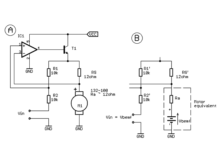
For applications with only moderate requirements you can implement closed loop control without a sensor by measuring the back-EMF of the motor.

You can even have a purely analog solution where the motor is driven by a power supply with negative output resistance to compensate for the motor resistance - this was used in Philips cassettes recorders 40 years ago.

This is a similar circuit to that used. The resistor Rs should be equal to the motor resistance measured when the motor is not rotating. The voltage across Rs increases with motor current and is fed back to increase the applied voltage to compensate for the voltage dropped by the internal motor resistance. The equivalent circuit in section B of the diagram helps explain the operation.

(Image from Precisionmicrodrives) Sensorless motor speed controller

\$\endgroup\$
0

Your Answer

By clicking “Post Your Answer”, you agree to our terms of service and acknowledge you have read our privacy policy.

Not the answer you're looking for? Browse other questions tagged or ask your own question.