2
\$\begingroup\$

I am working on pic24EP bootloader. My bootloader has it's own packet format to communicate with a python script to update the firmware of the microcontroller. The bootloader resides at the first free page after Interrupt Vector Table (0x000800). To make space for application, i have edited linker script of my application firmware so that application hex file wouldn't use any space in between 0x200 and 0x005BF0. The linker script of application project is given below:

/*
** Memory Regions
*/
MEMORY
{
  data  (a!xr)   : ORIGIN = 0x1000,        LENGTH = 0x8000
  reset          : ORIGIN = 0x0,           LENGTH = 0x4
  ivt            : ORIGIN = 0x4,           LENGTH = 0x1FC
  program (xr)   : ORIGIN = 0x6000,        LENGTH = 0x23FFE
  FICD           : ORIGIN = 0x2AFF0,       LENGTH = 0x2
  FPOR           : ORIGIN = 0x2AFF2,       LENGTH = 0x2
  FWDT           : ORIGIN = 0x2AFF4,       LENGTH = 0x2
  FOSC           : ORIGIN = 0x2AFF6,       LENGTH = 0x2
  FOSCSEL        : ORIGIN = 0x2AFF8,       LENGTH = 0x2
  FGS            : ORIGIN = 0x2AFFA,       LENGTH = 0x2
  FUID0          : ORIGIN = 0x800FF8,      LENGTH = 0x2
  FUID1          : ORIGIN = 0x800FFA,      LENGTH = 0x2
  FUID2          : ORIGIN = 0x800FFC,      LENGTH = 0x2
  FUID3          : ORIGIN = 0x800FFE,      LENGTH = 0x2
}

__FICD = 0x2AFF0;
__FPOR = 0x2AFF2;
__FWDT = 0x2AFF4;
__FOSC = 0x2AFF6;
__FOSCSEL = 0x2AFF8;
__FGS = 0x2AFFA;
__FUID0 = 0x800FF8;
__FUID1 = 0x800FFA;
__FUID2 = 0x800FFC;
__FUID3 = 0x800FFE;
__CODE_BASE = 0x6000;
__CODE_LENGTH = 0x23FFE;
__IVT_BASE  = 0x4;

__DATA_BASE = 0x1000;
__DATA_LENGTH = 0x8000;

It looks like my bootloader rejects firmware (hex file) at some point as it has address in between 0x200 and 0x005BF0 but i have edited the application linker script to only use addresses above 0x6000 by modifying variables: __CODE_LENGTH and program.

The memory map of my micro-controller is below:

Memory Map Image

The size of flash is 256kB and page size is 1024 instructions (1024*4 Bytes). The Hex File is over here. And the linker script is over here.

EDIT: I have solved my problem. Looks like PIC uses a slighty different HEX File Format than INTEL. The addresses in HEX file are 2 times the real address in PIC. So, i need to divide the address in hex file by 2 to get flash address of PIC microcontroller.

However, i have identify new issue with my system. I am not able to post a new question. So, i am adding it here. Now, my application(well tested) uploaded via bootloader works until any interrupt fires up. If any interrupt fires up, it hangs. All i can check is that it doesn't end up in any trap. Can anyone point me to right direction?

\$\endgroup\$
9
  • \$\begingroup\$ Whats your question? Can you post the hex file somewhere? What format is the hex file in? Is it possible your receive function on the pic is incorrectly parsing your commands from your python script? \$\endgroup\$
    – gregb212
    Commented May 31, 2017 at 18:42
  • \$\begingroup\$ I have checked my python script. My python script doesn't do much. It sends hex file line by line. PIC bootloader interprets those lines and write flash. \$\endgroup\$
    – abhiarora
    Commented May 31, 2017 at 19:02
  • \$\begingroup\$ If you are getting an invalid address than either your hex file is incorrect or you have transmission issues. Can you post your hex file somewhere? \$\endgroup\$
    – gregb212
    Commented May 31, 2017 at 20:37
  • \$\begingroup\$ Sure! Check my question again. I have added link to hex file \$\endgroup\$
    – abhiarora
    Commented May 31, 2017 at 21:33
  • 1
    \$\begingroup\$ Assuming the hex file is in intelhex format, it looks like in the hex file you pasted, addressing starts at 0x0000 and goes up to 0x055FF0. The meaningful data stops at 0x12E00, with a few bytes all the way at 0x055FE0 I dont think this is what youre expecting? \$\endgroup\$
    – gregb212
    Commented May 31, 2017 at 22:16

3 Answers 3

2
\$\begingroup\$

I have successfully completed bootloader for pic24EP256GP204. There were two issue with my bootloader:

  1. The first bug in my bootloader was in interpreting HEX file format for pic microcontrollers. The address field in the hex file is double that of the PIC device address. I didn't know that. I was using that address directly without dividing it. So, i need to divide the address in a record of hex file by 2 and should use that address for programming pic.

  2. The second bug was in writing the flash. My pic (pic24ep256gp204) supports double instruction flash write operation only. I was making a small mistake in writing the instructions if we need to write a single instruction. I found some code online using it i can write a single instruction by masking either the upper or lower instruction with a double instruction flash write operation. The code i found is pasted below:

    unsigned NVMemWriteWord(uint32_t address, uint32_t data)
    {
    DWORD_VAL writeAddress;
    DWORD_VAL writeData;
    
    writeAddress.Val = address;
    writeData.Val = data;
    
    NVMCON = 0x4001;        //Perform WORD write next time WR gets set = 1.
    NVMADRU = writeAddress.word.HW;
    NVMADR = writeAddress.word.LW;
    
    // Set the table address of "Latch". The data is programmed into the FLASH from a temporary latch. 
    TBLPAG = 0xFA;
    //The smallest block of data that can be programmed in
    //a single operation is 2 instruction words (6 Bytes + 2 Phantom Bytes).
    // Mask the high or low instruction words depending on the address and write either high or low instruction word.
    if(address % 4)
    {
        __builtin_tblwtl(0, 0xFFFF);                //Mask the low word of 1-st instruction into the latch.
        __builtin_tblwth(1, 0x00FF);                //Mask the high word of 1-st instruction into the latch. (8 bits of data + 8 bits of "phantom data" (phantom byte is always 0))
    
        __builtin_tblwtl(2, writeData.word.LW);     //Write the low word of 2-nd instruction into the latch
        __builtin_tblwth(3, writeData.word.HW);     //Write the high word of 2-nd instruction into the latch        
    
    }
    else
    {
        __builtin_tblwtl(0, writeData.word.LW);     //Write the low word of 1-st instruction into the latch
        __builtin_tblwth(1, writeData.word.HW);     //Write the high word of 1-st instruction into the latch 
        __builtin_tblwtl(2, 0xFFFF);                //Mask the low word of 2-nd instruction into the latch.
        __builtin_tblwth(3, 0x00FF);                //Mask the high word of 2-nd instruction into the latch. (8 bits of data + 8 bits of "phantom data" (phantom byte is always 0))
    
    }       
    
    INTCON2bits.GIE = 0;                            //Disable interrupts for next few instructions for unlock sequence
    __builtin_write_NVM();
    while(NVMCONbits.WR == 1){}
    INTCON2bits.GIE = 1;                            // Re-enable the interrupts (if required).
    
    // Return WRERR state.
    return NVMCONbits.WRERR;
     }
    
\$\endgroup\$
1
\$\begingroup\$

Sort of expanding my comment here. I'm not 100%, but the hex format appears to be intelhex. I'm using the hex viewer provided by the Segger JFlash program to view the contents of the hex file.

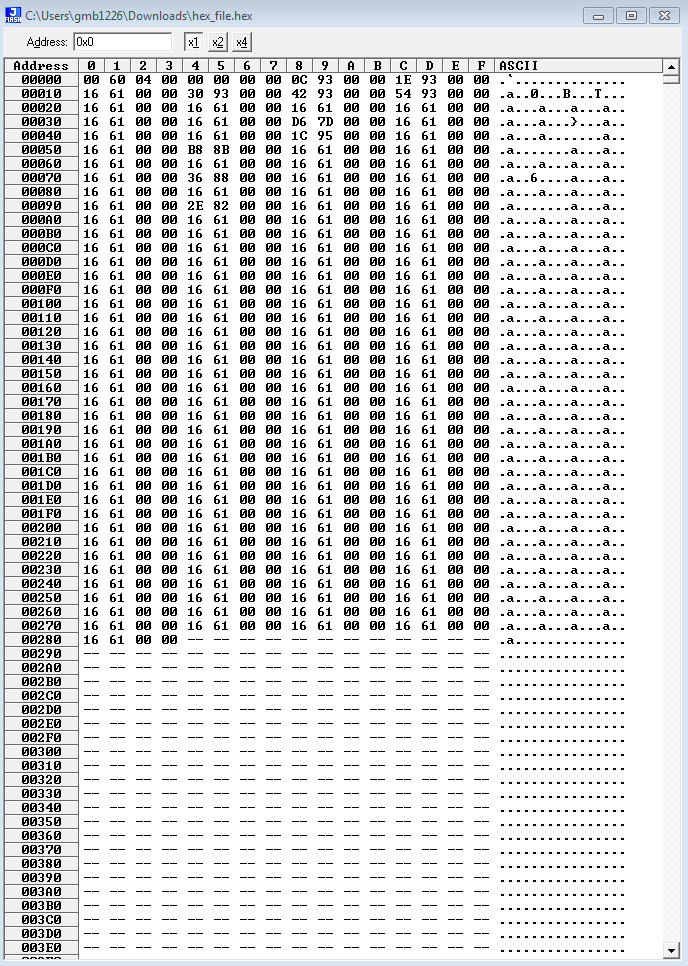
Your addresses are starting at 0x0, no doubt about it. If your python script is naively sending the bytes to your mcu, then it will indeed send addresses within the 0x200-0x005BF0 range. I've attached a snip of your hex file illustrating that the base address of the hex file is 0x0.

Did you point your linker to the correct .ld file?

Quick fix is to simply ignore these out-of-bounds addresses with your python script. You could also ignore out-of-bounds on the mcu side, but this may lead to nasty silent bugs when it isn't fully flashed.

A more thorough fix is to figure out why the linker script isn't doing what you're telling it to. I am unfamiliar with pic's linker language, but I've done something similar with a Cortex M-0 core and a GCC toolchain. I highly recommend searching for a guide. Your use case is not unusual and I am sure it is documented. I apologize I cannot offer more guidance, but a quick google of "pic bootloader linker script" produced some promising results.

A snip of your uploaded hex file, illustrating contents at 0x200. Snip of hex file demonstrating base address at 0x0

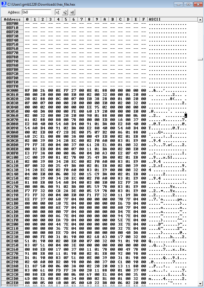
It remains blank until 0xC000, where it appears you application starts: enter image description here

EDIT TO RESPOND TO EDITED QUESTION:

You need to debug this new issue. It sounds like your vector table was corrupted. Use a tool such as MPLAB IPE to download the flash contents of your MCU and verify that your mcu bootloader is not doing anything silly to your vector tables.

\$\endgroup\$
10
  • \$\begingroup\$ Thanks for your help. Please have it a look at the linker file i have posted pastebin.com/gB2YimWC \$\endgroup\$
    – abhiarora
    Commented Jun 1, 2017 at 8:19
  • \$\begingroup\$ I am not pushy but can you just look at my linker file? I have tried numerous solutions \$\endgroup\$
    – abhiarora
    Commented Jun 3, 2017 at 6:41
  • \$\begingroup\$ I did, but I am not an expert on linker files. Does your linker complain about using the new file? Try intentionally injecting bad linker commands to see if your linker is even using the right ld file. Are your memory regions continuous? I seem to remember having to ensure there are no gaps in the sections. \$\endgroup\$
    – gregb212
    Commented Jun 3, 2017 at 15:39
  • \$\begingroup\$ If you cant get the hex file to respond to your modified linker, no matter what you have tried, then do a sanity check. Start a brand new project with a simple main and try to modify the linker there. Try using an xc8 compiler instead, maybe. Just try to get the linker to accept your commands first, then worry about what you really need it to do. \$\endgroup\$
    – gregb212
    Commented Jun 3, 2017 at 15:49
  • \$\begingroup\$ Hey man! I got a clue. I have checked my Linker file of application and it says 0x6000 will be the start of the application (you can check my hex file at address 0x000 (RESET VECTOR)). But the hex file MPLAB is generating something else? Look at the screenshots you have posted. The address starts at 0xc000 \$\endgroup\$
    – abhiarora
    Commented Jun 3, 2017 at 20:59
1
\$\begingroup\$

As another troubleshooting method for PIC bootloader's, you can add the bootloader MPLABX project as a "loadable" of your main application project. The compiler will then give you warnings on any memory overlaps or conflicts as defined by your individual linker files.

To add a loadable, right click your application project and click properties. Under Conf/Loading select your bootloader project.

\$\endgroup\$

Your Answer

By clicking “Post Your Answer”, you agree to our terms of service and acknowledge you have read our privacy policy.

Not the answer you're looking for? Browse other questions tagged or ask your own question.