0
\$\begingroup\$

My questions:

  1. Why would the drain to source current of MOSFETS suddenly increases.
  2. What can be done to resolve it?

I am aware that there is supposed to be an increase in current as soon as the gate voltage of the MOSFET reaches the threshold voltage, but I would like to determine whether the behavior of my electronic load is typical because the increase seems too sudden given my minimal increase in voltage.

Introduction to setup and circuit

I am building an electronic load that uses three parallel IRF640 to control the current. It is for testing our solar panel strings so the voltage applied to it is approximately 100V at open circuit and it will receive a current of at most 2.5A. This is within the maximum values of the MOSFET. I have addressed the maximum power problem/heating of the MOSFETS by adding 20 ohms 400 Watts in series to the drain of the MOSFET, so it does not heat up by a noticeable amount at any point. The MOSFETS are also attached to a heat sink to minimize heating further.

Here is my circuit (I'm unable to add images directly)

The circuit behaves as expected at around 40Vds. As I slowly increase the voltage applied to the gates of the MOSFETs, the drains to source current steadily increases.

Problem

The problem occurs whenever I increase the voltage across the drain to source. Initially the current would increase as expected in earlier tests, but as I reach 4.1V or somewhere around that number, the drain to source current suddenly jumps from a mere 0.7A to 3A (maximum current of supply).

Here's an example of my tests at 80v Vds

Vgs -- Ids

0 ---- 0

1V ---- 0A

.

.

.

3V ---- 0A

3.2V -- 0.1A

3.4V -- 0.2A

3.6V -- 0.3A

3.8V -- 0.5A

4.0V -- 0.7A

4.1V -- 3A <--- As you can see here. It suddenly jumps up at the tiny increase in gate voltage

\$\endgroup\$
1
  • \$\begingroup\$ How you get these currents? Suddenly jumps means any time for that ramp? You just crossed Vgsth from MOSFET datasheets. \$\endgroup\$
    – user19579
    Commented Jun 5, 2017 at 6:25

4 Answers 4

0
\$\begingroup\$

1) This is the 'gate source threshhold voltage', broadly equivalent to the 0.7v Vbe in bipolars.

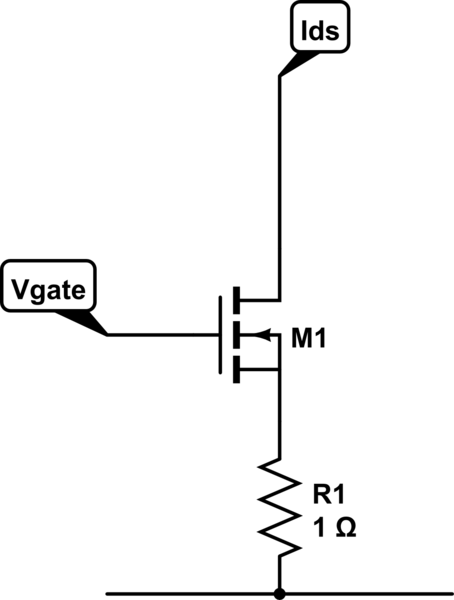
2) If you are building an electronic load, and 'controlled current' (or thereabouts) is an acceptable control law for your application, then you can add a power resistor with low resistance in series with the source terminal.

schematic

simulate this circuit – Schematic created using CircuitLab

As the Ids increases, so will the voltage drop across the source resistor, applying negative feedback to the supplied gate voltage, and so stabilising the current. The resistor will need sufficient power rating to tolerate your maximum current.

With (for example) 1\$\Omega\$ in series with your the source terminal of your example FET, the voltage/current would go approximately

Vgate -- Ids

3v -- 0A
3.6V -- 0.2A
4.3V -- 0.5A
4.7V -- 0.7A
7.1V -- 3A

As you see, voltage across the source resistor gets added to the input voltage, linearising the Gate voltage to Ids control law. Note this is Vgate with respect to ground, not Vgs.

As the threshhold voltage varies from part to part, with temperature, and with Vds, this is not an accurately controlled Vg->Ids control law, but is enough to tame it. If you want an accurate current source, then you can drive the gate with an op-amp, sensing the voltage on R1, and comparing that with a control voltage.

WARNING It's a little appreciated fact that FETs do not make good linear power transistors, they are designed for switching applications. A FET is made with multiple parallel connected cells, which when full-on share current nicely (their resistance has a positive tempco), but when biassed just on (as for a current load like this) do not share well (their Vgs has a negative tempco).

This limits the linear power dissipation to well below what you would expect. You say in the OP that 'this is within the maximum power values of the MOSFET'. Where did you get this figure from? Look at the SOA graph (fig 8 in the Vishay note) and notice that it does not have a curve for times > 10mS. If you want to extrapolate this graph down towards DC and estimate what the power would be at 1 second or 1 minute, then that's at your risk. You could try to interpret fig 11 as telling you something about thermal time constants, but whether they are the relevant time constants ...

You have several options
1) Estimate a low maximum power for IRF640s, keep well heatsinked, and hope they don't fail
2) Use a 'linear rated' FET, difficult to find and expensive
3) Use a power darlington bipolar transistor, similar power ratings but specified for the job (they have a 'DC' line on their SOA graph), and reasonable base drive, even if not zero like a FET.

In your application, increase the size of your R3 drain resistor to dissipate all of the power at maximum current, this will minimise the dissipation in your FETs.

As you are using several FETs, and this is only a solar panel loading exercise, you might want to consider separating the FETs, giving each a different drain resistor, and switching them on and off to make a very crude power DAC. It would only give you 8 resistance settings for 3 control bits, and obviously the current would vary with applied voltage, but it may be sufficient for your application, and you wouldn't need to worry about FET power rating, or even need to heatsink them much.

\$\endgroup\$
2
  • \$\begingroup\$ If I switched to a darlington BJT, would adding an op amp still be beneficial? \$\endgroup\$
    – unknownr
    Commented Jun 5, 2017 at 5:53
  • \$\begingroup\$ It depends how 'constant' you want the current to be. If 'very', then yes. If 'roughly', then no, at least when used with an R1 from emitter to ground in the same way as above. Note that there is a smaller variation of Vbe part to part for bipolars (as it's a material constant) than Vgs-th for FETs (which is more about geometry). \$\endgroup\$
    – Neil_UK
    Commented Jun 5, 2017 at 7:39
1
\$\begingroup\$

There is nothing magic about the power darlington BJT; its even more prone to thermal runaway than is the power MOSFET.

With the heating being the base-collector region, just 1micro below the emitter-base region, the runaway timeconstant is just 11.4 nanoseconds or so. (11.4 nS is the thermal tau of 1 cubic micron of silicon). With a fixed Vbe, and an internal-reducing Vbe of -2.2 milliVolts/degreeCentigrade, times 1 amp*5 volts (some power numbers), times 10 degreeCentrigrade/watt, times 4 milliVolts per 10% delta Ie (or Ic), we perturb these numbers (the 4milliVolts is our perturbation).

If a 4 millivolt perturbation produces more than 4mV output, you have a thermally unstable box (gain > +1 ).

What do we have here? 4mV => 10 % deltaI => 0.1 amp deltaI. DeltaPower is 5 volts * 0.1amp, or 0.5 watts. The deltaTemp is 0.5 watts * 10 degreeCent = 5 degreeCent. And knowing -2.2 milliVolts/degreeCent, we scale by 5, to get 11 milliVolts.

Since 11mV > 4mV, you would be thermall unstable.

FETS have similar math, using different numbers.

\$\endgroup\$
1
\$\begingroup\$

You have just demonstrated a phenomenon known as thermal-runway. The tempco of Vgs is negative, its specifics value varies from device to device versus the approximate -2mV/degC of a bjt. However as your fet heats up its Vt declines, and as a result turns on harder. The process repeats and repeats until it is hogging significant current.

\$\endgroup\$
0
\$\begingroup\$

It's about MOSFET's Gate-Source Threshold Voltage, \$V_{gs-th}\$. Open datasheet, under "SPECIFICATIONS" on p.2, you'll see a parameter named "Gate-Source Threshold Voltage". It has a maximum value of 4V though.

For gate-source voltages lower than threshold, MOSFET does not turn on completely.

If you want lower threshold voltages then use MOSFETs with "Logic level gates". They are perfect for driving from MCUs. IRL640 is the logic level equivalent of your MOSFET.

\$\endgroup\$

Your Answer

By clicking “Post Your Answer”, you agree to our terms of service and acknowledge you have read our privacy policy.

Not the answer you're looking for? Browse other questions tagged or ask your own question.