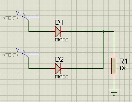
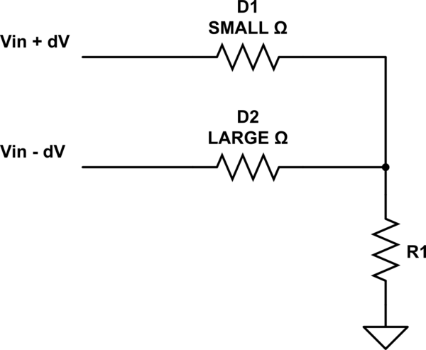
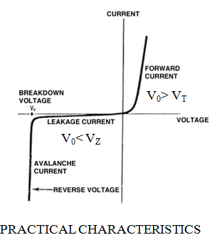
I saw this circuit in an electronics' book . In the first image , the voltage sources are the same for the 2 diodes, that's mean every diode will have 0.7 V and the resistor will have 4,3 V.
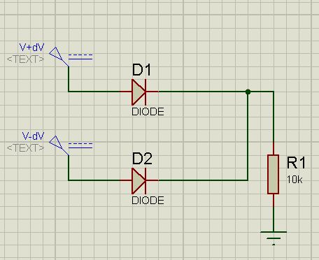
The problem was with the 2nd image, if I increase the first source voltage by 1 mV and decrease the second by 1 mV , the answer that the resistor will maintain its voltage to 4.3 V but what will change is the diode voltage :
Vd1 = 5.001 - 4.3 = 0.701;
Vd2 = 4.999 - 4.3 = 0.699;
Can anyone tell me what will happen in the 2nd circuit, more explanations by a circuit analysis or any method to understand.

