1
\$\begingroup\$

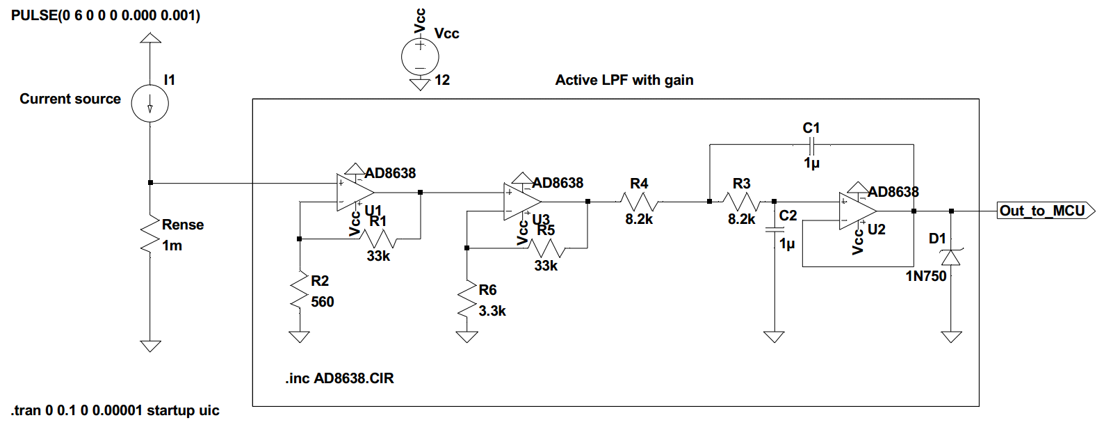
I'm trying to sense the current through a wire, and so far I decided to use a 1mOhm shunt resistor to convert it to voltage. As you see in the below circuit, the current source I1 sources 6A amplitude PWM current pulses(freq. is 1kHz). The idea is to adjust the current by the PWM coming from a uC.

But I also want to regulate this current and for that I need the uC to sense the current. So far I came up with the following circuit which is a LPF with gain:

enter image description here

Above the active LPF here mappes the PWM current to a 0 to 4V DC voltage which will go to one of the ADC of the microcontroller.

The opamp I use is a special amplifier with very low offset drift. In simulation only this opamp works the rest I tried all causes significant offset in simulation.

The LPF by the way has 20Hz cut off and designed by the filter design tool.

Eventhough this works in simulation, Im not happy with this interface. First of all, it is SMD and has many cascaded staged to solder.

So my question is:

1-) Is there an alternative easier way to sense this current here. Like a single DIP IC which translates the current to voltage with less soldering effort? Or any other single chip DIP LPF?

2-) How about instead of averaging current by a LPF, what alternative way could be use to send the actual current information as voltage to uC ADC? (I thought measuring the duty cycle but that didn't make sense because I already know the duty cycle which is coded to the uC)

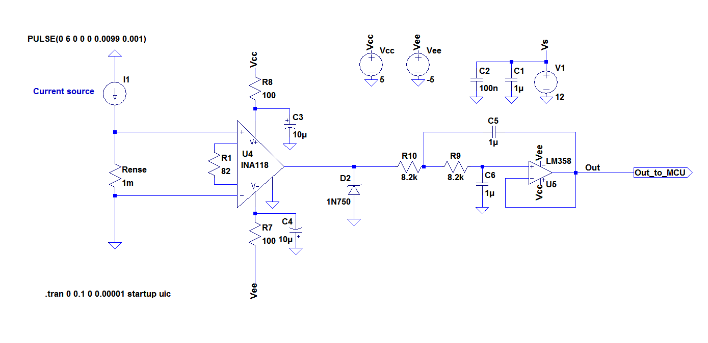
Edit:enter image description here

I'm unable to solder SMD.

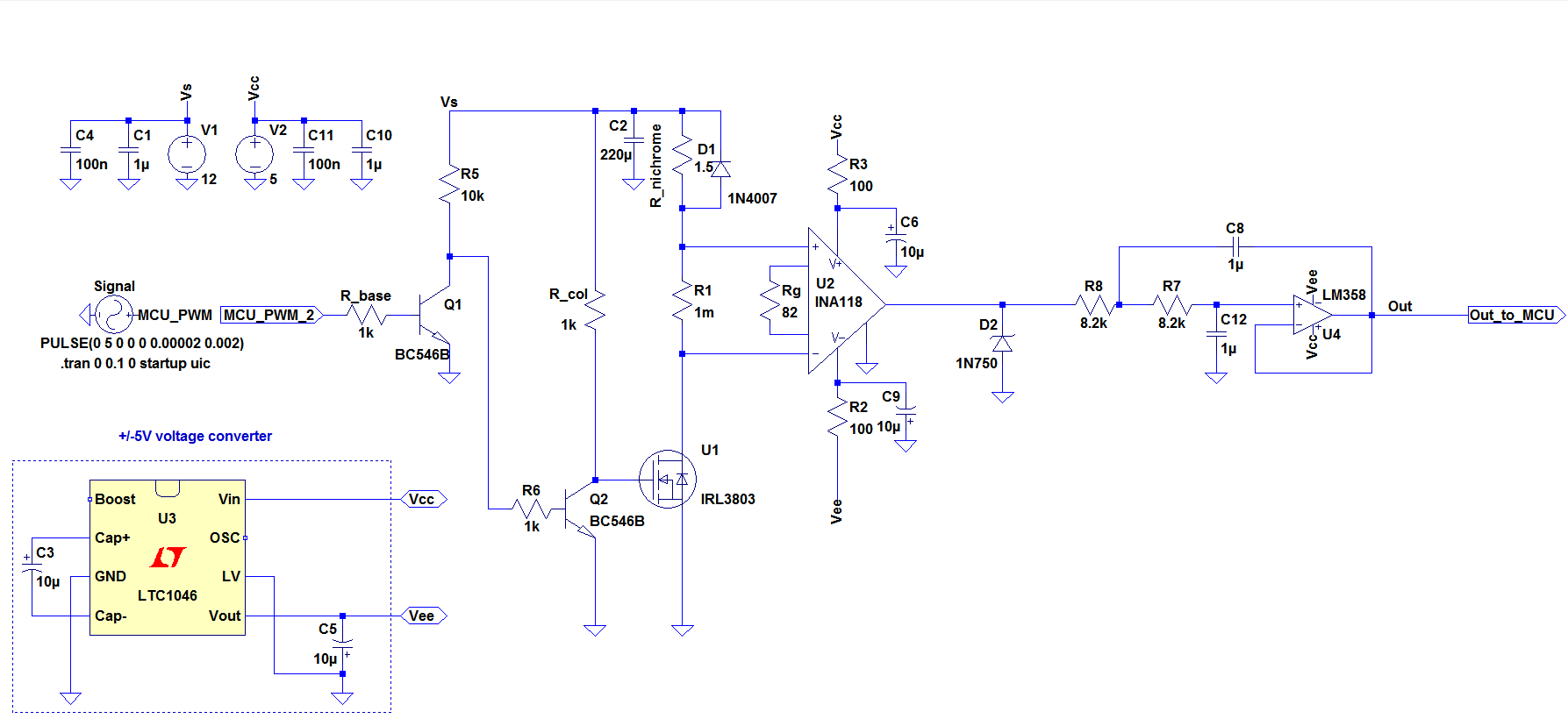
Edit2:Entire circuit(NPNs might not be needed):

enter image description here

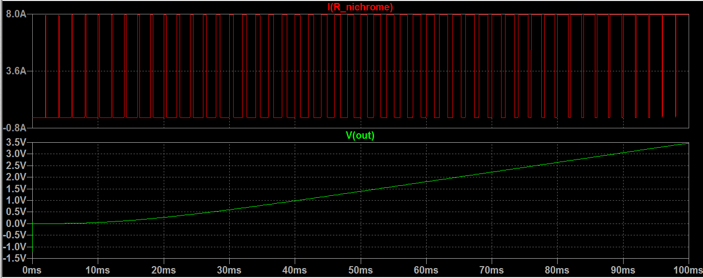
PWM Sweep and the output:enter image description here

\$\endgroup\$
14
  • \$\begingroup\$ only the first op-amp needs to be a super duper autozero type, the second is working with a much bigger signal. I'd be inclined to put a single stage RC on each of the first two amps, and ditch the 2nd order SK filter. Same ultimate rate of rejection, just slightly soggier passband and corner performance. \$\endgroup\$
    – Neil_UK
    Commented Jun 8, 2017 at 17:09
  • \$\begingroup\$ would using a hall effect sensor work to translate 0..6A current to voltage for the ADC? Would a hall effect sensor measure PWM current? \$\endgroup\$
    – floppy380
    Commented Jun 8, 2017 at 17:15
  • \$\begingroup\$ @Neil_UK What do you think about the second circuit? Please see my edit. I used an inamp. This inamp is DIP \$\endgroup\$
    – floppy380
    Commented Jun 8, 2017 at 17:26
  • \$\begingroup\$ Please also see my last edit I added the entire circuit. I also added simulation with PWM swept and the output to ADC. I would like to have your opinion for a real life implementation., \$\endgroup\$
    – floppy380
    Commented Jun 8, 2017 at 17:39
  • \$\begingroup\$ I am not sure if there is any DIP version of Allegro Hall-effect sensors. But if you google ACS711, or similar parts, you will see how they work. Something like that might work for you if you can find a DIP version. Also, the SOIC version pins are fairly large and easy to solder by hand, even though they are SMT. \$\endgroup\$
    – user57037
    Commented Jun 8, 2017 at 17:56

2 Answers 2

1
\$\begingroup\$

How much current do you need to measure?

When using such a low resistance you need to be aware of the difference between simulation and realization. For a 1m ohm resistor you'd need kelvin connections to read appropriate values and make sure you have really low noise all around.

Search texas instrument for low-side current measurement and you'll get off the shelf chips with the internal resistance.

This one is digital output: http://www.ti.com/lit/ds/symlink/ina260.pdf

This one has analog output with gains from 200mv/a to 2V/A http://www.ti.com/product/ina250

Search also maxim, analog, st, etc. There are a lot of products like this.

Cheers,

\$\endgroup\$
10
  • \$\begingroup\$ These are also all SMD \$\endgroup\$
    – floppy380
    Commented Jun 8, 2017 at 17:16
  • \$\begingroup\$ What do you think about the second circuit? Please see my edit. I used an inamp. this inamp is DIP \$\endgroup\$
    – floppy380
    Commented Jun 8, 2017 at 17:27
  • \$\begingroup\$ Please also see my last edit I added the entire circuit. I also added simulation with PWM swept and the output to ADC. I would like to have your opinion for a real life implementation., \$\endgroup\$
    – floppy380
    Commented Jun 8, 2017 at 17:39
  • \$\begingroup\$ SMD looks more scary than it is. Don't be afraid of it you'll need it sooner or later and you open yourself to a lot more options. Think it this way, it will take you less time to solder your SMD than to redesign a whole circuit you can just get in one SMD chip. \$\endgroup\$
    – Andrés
    Commented Jun 8, 2017 at 22:54
  • \$\begingroup\$ i dont know how to solder SMD and dont have the right tools. even i tried many times i still even suck in normal soldering. the only thing i HATE electrical is soldering. i know people they know nothing about theory but they make amazing boxes with electronics circuits. just because they have stable hand and have hands on talent. i want something DIP on perfboard for this personal project. \$\endgroup\$
    – floppy380
    Commented Jun 8, 2017 at 23:05
0
\$\begingroup\$

Circuit 2 is not terrible, but there are a few changes you might make.

1) R6 is unnecessary, since if Q1 pulls down below ~0.5 volts Q2 will be turned off, and when Q1 is off, the 10k will drive the base of Q2.

2) With a PWM frequency of 1 kHz, your gate drivers will be OK, but not for much higher frequencies. On the one hand, your FET has an input capacitance of (nominally) 5 nF, and with an r_col of 1k your time constant is about 5 usec. This is no problem for turn-on, since the 1 volt Vgs(th) will produce a fast turn-on, but there will be a very large delay (about 10 usec) for a turn-off signal to take effect. The gate will have to drop from 12 to 1 volt, so this will take about 2 time constants. This is not a problem at 1 kHz, but at 100 kHz you'd have real problems.

3) Most important, you're better off moving your sense resistor to between source and ground. The added voltage (6 mV) will not affect switching noticeably, but your current position causes major common-mode swings at the IN118's inputs. Not only that, but the inputs will go to 12 volts, and that is not usually a good thing to do for an amp powered by +/- 5 volts. Granted, the IN118 is protected to 40 volts, so you won't get in trouble with this particular circuit, but it's bad practice to get into the habit of depending on protection which may not be there if you change amps. In other words, your choice of position will not cause much difficulty with this particular circuit, but you're better off if you develop good design habits. Plus, if your wiring is such that you get inductive spikes while switching the heater, those spikes may well exceed the 40 volt limit. While you have a flyback diode, your wiring harness may have effects which don't show up on your simulation.

4) Using a zener directly on the output of an op amp is never a good idea for voltage limiting.

5) Personally, I'd suggest that you should use 10 ohms rather than 100 for your power supply input isolation resistors for the IN118, particularly if you're going to keep that zener. In ordinary operation the current requirements are low enough to use 100 ohms, but if the zener tries to limit in either direction you will get a current surge, and that's not a great idea with those resistors.

6) While you have very properly established a Kelvin connection from the sense resistor to the amp, be careful about your realization in hardware, particularly if you're using a PCB layout tool with an autorouter. I guarantee that the autorouter will make a mockery of your connection.

So overall, I expect your circuit will work OK. My suggestions are in the nature of improvements rather than major objections.

\$\endgroup\$
2
  • \$\begingroup\$ thanks I will review the circuit with yours and other suggestions and i will write back here and to you with an updated one as soon as possible. \$\endgroup\$
    – floppy380
    Commented Jun 8, 2017 at 23:56
  • \$\begingroup\$ Since it would be a huge edit with new issues/questions I just opened a new question regarding this project: electronics.stackexchange.com/questions/310182/… I would be glad to have your input as well. Thanks. \$\endgroup\$
    – floppy380
    Commented Jun 10, 2017 at 13:18

Your Answer

By clicking “Post Your Answer”, you agree to our terms of service and acknowledge you have read our privacy policy.

Not the answer you're looking for? Browse other questions tagged or ask your own question.