1
\$\begingroup\$

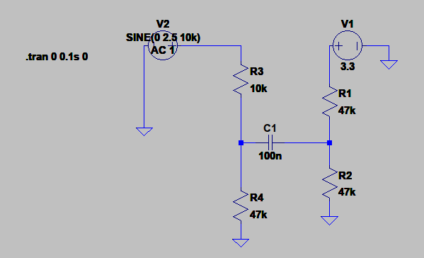
I'm trying to monitor speaker volume from its input signal. Input signal range is [-2.5; 2.5]V. I'm reading signal on an ADC with [0;3.3]V input range. I did a simple circuit :

  • reduce voltage amplitude to 3.3V
  • add a 3.3/2V offset

Here is circuit : enter image description here

Here are results of temporal and frequency simulations : enter image description here

enter image description here

From results I have several questions :

  • first I put a 22k R3 value in order to get a Vout/Vin ratio ~ 0.68 that reduces input voltage to a 3.3V amplitude. I got an output signal in [0.6; 2.6]V range. So I increased C1 without any changes, after I reduced R3 to 10k to fit in [0.1; 3.1]V. Why?
  • this circuit is simple, but how can I simulate how audio signal is deteriorated with this circuit?
  • do you have other circuits as suggestions?
\$\endgroup\$

2 Answers 2

2
\$\begingroup\$

You want to monitor a ±2.5 Vpp audio signal with a 0-3.3 V A/D. This means you need to reduce the amplitude and shift the result. The gain must be 3.3 / 5 = .66, or preferably a little less. You say this signal is being used to drive a speaker, so should be quite low impedance.

A capacitor, as you show, makes sense so that you can completely decouple the input and output DC levels. However, you don't need 4 resistors, and they don't need to be such high values. This should do:

R1 and the parallel combination of R2 and R3 form a voltage divider. R2 // R3 = 5 kΩ. The gain of the divider is therefore (5 kΩ)/(7.7 kΩ) = 0.65. 5.0 V in results in 3.25 V out.

C1 decouples the DC levels between IN and OUT. It is working against 7.7 kΩ impedance. At 2 µF, the rolloff frequency is 10.3 Hz, so 20 Hz and up is solidly in the pass band.

The values of R2 and R3 should really be dictated by the input impedance requirement of the A/D you are using, which you haven't told us. All three resistors are in parallel for the purpose of determining the impedance OUT is being driven with. In this example, that is 1.8 kΩ. You can scale all the resistors by the same value and still get the same attenuation and DC bias. However, the impedance driving OUT is scaled by the same value. For example, if you really wanted 1 kΩ output impedance, then scale all resistors by about 0.57. If you lower the resistances, you have to raise the capacitance to maintain the same high pass filter rolloff frequency.

I have no idea what you mean by audio being "deteriorated" by this circuit.

Added

Yes, when calculating the output impedance, you assume the input is being driven with zero impedance. Put another way, we are looking at the result of some voltage on IN. What factors cause that particular voltage don't matter. The voltage is what it is. Given that voltage, what will be the voltage on OUT, and how will that change as OUT is loaded?

\$\endgroup\$
2
  • \$\begingroup\$ Many thanks for response. Here is ADC spec : pjrc.com/teensy/K20P64M72SF1.pdf it is a SAR ADC with 4pF capacitance and 2kohm resistance. Could you detail this point " All three resistors are in parallel for the purpose of determining the impedance OUT is being driven with" , ? does that mean that a zero impedance voltage source is considered before R1? V1 signal is used as an amplifier input that drives a speaker. V1 is the result of a preamplification. So, I do not want some V1 frequencies be filtered by given circuit. \$\endgroup\$
    – rem
    Commented Jun 12, 2017 at 22:35
  • \$\begingroup\$ Another thing, from electronics.stackexchange.com/questions/22742/… , B = V1 * R1 / (R1 + R4) = 1.65, from given values => V1 = 7.7/2.7*B = 4.70, but should be ~1.65V, why? \$\endgroup\$
    – rem
    Commented Jun 13, 2017 at 7:04
0
\$\begingroup\$

What do you mean by "deterioration"? What is important to you. Changes in amplitude do not cause a deterioration of an audio signal.

With the values you have shown there will be a small reduction in the bass response but that may not be important to you. This can easily be changed by increasing the value of C1.

High quality audio approximately covers the range 20Hz to 20kHz. This is subjective many people cannot hear above 10-12kHz and it decreases with the person's age. Many loudspeakers cannot cover the low-end and the output may fall significantly below ~200Hz.

Voice quality requires only 300-3000Hz.

\$\endgroup\$

Your Answer

By clicking “Post Your Answer”, you agree to our terms of service and acknowledge you have read our privacy policy.

Not the answer you're looking for? Browse other questions tagged or ask your own question.