0
\$\begingroup\$

I want to understand how to think about a capacitor in an electrical circuit. Note: I'm looking for an explanation of the basics that would help me answer this question, not an advanced discussion of the topic.

Consider a circuit with a battery with an EMF of E_batt, a capacitor, and a resistor. The voltage at the capacitor & the resistor may be related to the EMF of the battery by the following:

$$E_{batt} =V_c + V_r \tag{1}$$

My understanding is that because current decreases exponentially during the charging of a capacitor, it will produce a voltage V_c in the opposite direction to the battery's E, so that the net voltage across the circuit is:

$$V_{net} = E_{batt} - V_c \tag{2}$$

Therefore, I can replace V_r in Eq. 1 with E - V_c, thus equating E_batt to itself. To me, this proves the relationship observed in Eq. 1.

However, after considering the smoothing of a bridge rectifier, I think that my logic is flawed. The voltage across the capacitor does not technically 'oppose' the voltage across the battery. It seems like whichever component has a higher voltage, capacitor or power supply, takes over the circuit. The voltages don't seem to interact at all, except when the voltage across a capacitor drops to below the voltage across the power supply.

Why is the sum of the potential differences across across the capacitor and the resistor equal to the emf across the battery?

More importantly, when considering the smoothing of a bridge rectifier, why doesn't the voltage across the capacitor oppose the voltage across the power supply?

\$\endgroup\$
8
  • 6
    \$\begingroup\$ Kirchoff's Voltage Law \$\endgroup\$
    – The Photon
    Commented Jun 14, 2017 at 1:12
  • \$\begingroup\$ May you please address the confusion point about my way of thinking about a capacitor? Hang on, I will edit the question. \$\endgroup\$ Commented Jun 14, 2017 at 1:26
  • 1
    \$\begingroup\$ What do you mean by "the net voltage across the circuit is E-Vc"? The voltage across the resistor is Vr = E - Vc (by KVL) and this voltage determines the capacitor current Ic = Vr / r which then determines the rate of change of the capacitor voltage. \$\endgroup\$ Commented Jun 14, 2017 at 1:33
  • 1
    \$\begingroup\$ Well, your problem is this: "please don't provide high level explanations. I only require a very basic explanation." All you've embraced is only a hodge podge of simple explanations and now... you are confused. That's the result of scattered over simplification. As Einstein said, "It should be as simple as possible, but no simpler." When you are ready for a simple, but not simplistic (to the point of distortion and confusion) explanation, let us know. \$\endgroup\$
    – jonk
    Commented Jun 14, 2017 at 3:57
  • \$\begingroup\$ Every two terminal component enforces some kind of rule. When you connect them all together, they essentially negotiate the voltage and current that satisfies all the rules. For a capacitor, the rule is I=C * dv/dt. Or, C = I / (dv/dt). So a change in voltage causes current to flow in or out of the capacitor. Or vice-versa. Cause and effect can go either way. But the rule must be satisfied. \$\endgroup\$
    – user57037
    Commented Jun 14, 2017 at 7:02

3 Answers 3

1
\$\begingroup\$

Let's start with E=Vc+Vr in a circuit with a battery of emf E and a capacitor of and a resistor.

This has nothing to do with any special property of capacitors or resistors. Consider this circuit:

schematic

simulate this circuit – Schematic created using CircuitLab

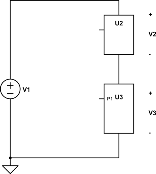
Regardless of what the U2 and U3 are, Kirchoff's Voltage Law (KVL) tells us that \$V_1 = V_2 + V_3\$.

This is true if U2 is a resistor and U3 is a capacitor or if U2 is one coil of a transformer and U3 is a spark gap.

My understanding is that the capacitor produces a voltage Vc in the opposite direction to the battery's emf E,

I think using the word "opposing" in this description is a bit confusing. It's really simple once you get the hang of it.

Consider the circuit above where U2 is a short circuit (so \$V_2\$ is 0). Then you have \$V_1 = V_3\$. The source is connected directly across U3, so the voltage across U3 is exactly equal to the source voltage. When we say it's "opposing" the source voltage we just mean that the reference direction of U3 is opposite the reference direction of V1 (which is why we've had \$V_1\$ on one side of the equals sign and \$V_3\$ on the other side in our KVL equations).

Again KVL requires this to be true, no matter what kind of component U3 is. It could be the b-e junction of a transistor. It could be a coil of a transformer. It could be a resistor. Or it could be a capacitor. In all cases, the voltage \$V_3\$ must be equal to \$V_1\$ with opposite reference direction.

\$\endgroup\$
11
  • \$\begingroup\$ Perhaps a little too much exuberance in the example of a spark gap if it is not actively conducting. \$\endgroup\$
    – Glenn W9IQ
    Commented Jun 14, 2017 at 2:43
  • 1
    \$\begingroup\$ @GlennW9IQ, even if it's not conducting, KVL says the voltages must add up. Even if U3 is a totally open circuit, KVL says the voltages must add up. (Obviously this is limited to lumped circuits, or KVL itself won't be valid) \$\endgroup\$
    – The Photon
    Commented Jun 14, 2017 at 2:56
  • \$\begingroup\$ KVL applies for any round trip choice of nodes in a circuit whether there's components connecting the nodes or not. We just usually choose a sequence of nodes connected by nodes because then the component constitutive equations actually let us solve the circuit. \$\endgroup\$
    – The Photon
    Commented Jun 14, 2017 at 2:57
  • 2
    \$\begingroup\$ @GlennW9IQ, simply not true. If it was, KVL wouldn't apply to a loop containing a capacitor at DC. \$\endgroup\$
    – The Photon
    Commented Jun 14, 2017 at 3:16
  • 1
    \$\begingroup\$ @GlennW9IQ, you must choose a closed sequence of nodes (i.e., start and end on the same node). But there don't have to be current paths (circuit branches) connecting the nodes in the sequence you selected. (Again, it's more useful for circuit analysis to choose nodes connected by branches, but it's not a requirement for KVL). \$\endgroup\$
    – The Photon
    Commented Jun 14, 2017 at 3:18
0
\$\begingroup\$

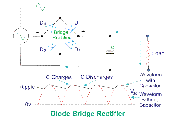
Keep in mind the capacitor opposes changes in voltage across itself. It takes some finite amount of time for the voltage across capacitor to change. You may think of this as inertia offered by the capacitor to changes in voltage. This is a basic defining property of capacitor. We use this inertia property of the capacitor to our advantage in a bridge rectifier by connecting the load across capacitor. Since voltage is same across parallel branches, our load sees the same voltage that appears across capacitor. And since the capacitor hates changes in voltage, our load is kinda protected from sudden changes in voltage. enter image description here

In an rc series circuit, assuming capacitor's initial voltage is 0, as soon as you connect the supply, the capacitor doesn't like to change its voltage, so all the voltage appears across the resistor; As time goes on, capacitor lazily charges, slowly increasing its voltage. At the same time the voltage across resistor decreases. This goes on forever. If you wait long enough time, almost all the battery voltage appears across capacitor and 0 voltage across resistor and the current ceases in the circuit.

\$\endgroup\$
0
\$\begingroup\$

why doesn't the voltage across the capacitor oppose the voltage across the power supply?
It does. KVL states that the sum of voltages in a closed loop should be zero. Consider voltages to be applied clockwise or counterclockwise, and you will see that \$V_c\$ is applied in the opposite direction to \$E_{batt}\$:

schematic

simulate this circuit – Schematic created using CircuitLab

\$\endgroup\$

Your Answer

By clicking “Post Your Answer”, you agree to our terms of service and acknowledge you have read our privacy policy.

Not the answer you're looking for? Browse other questions tagged or ask your own question.