0
\$\begingroup\$

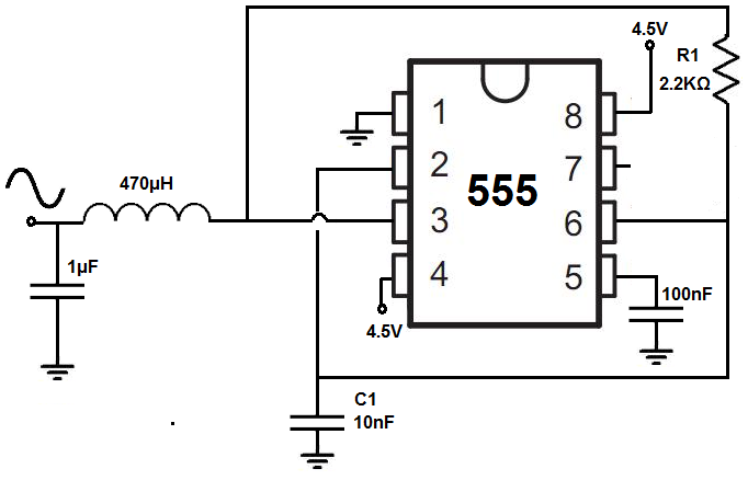
I was looking at how to get a sign wave from a 555 chip and found this article.

enter image description here

It seems to say it's using an astable 555 circuit outputting to an LC resonant circuit.

However, the circuit diagram does not match up with any astable 555 circuit I can find anywhere else, and although he has some examples of different value components for different outputs, it might be easier to work with a standard astable 555 circuit.

I found this question regarding alternate astable 555 circuit designs, but the design in the linked article is different again, it doesn't use the discharge pin (pin 7). Functional difference between various astable 555 circuits

Are there benefits to this alternate circuit for this use case? Would you be able to describe how this is functionally different, especially how the RC network he refers to comes into it. Would calculations for resistors and capacitors in other circuits work for this one? Finally, would the LC resonant circuit on the output, calculated for the correct frequency, work for any square wave source, including the standard 555 astable circuit?

\$\endgroup\$
1
  • \$\begingroup\$ Indeed, not sure how I missed that \$\endgroup\$ Commented Jun 15, 2017 at 7:37

2 Answers 2

1
\$\begingroup\$

The "closest" sinewave-like signal you can get from the output of a 555 is when the Duty Cycle is 50 %. As much high as it is low. Then when you filter that (for example with an LC circuit) you get something close to a sine-wave.

The 555 in its basic circuit will always give a duty cycle of more than 50% as the discharge time is shorter than the charge time and the output is high during the charge time.

There are several modifications one can make to the basic 555 circuit to fix this. One solution is to use the 555 as a window comparator which is what is done here.

How you get to the 50% Duty Cycle is largely irrelevant. More relevant is to match the signal frequency to the resonance frequency of the LC circuit and to use a buffer as not to load the LC circuit as then Q will decrease and filtering will be worse resulting in a worse quality sinewave.

\$\endgroup\$
3
  • \$\begingroup\$ What do you mean by a buffer and what Q are you referring to? \$\endgroup\$ Commented Jun 15, 2017 at 8:08
  • \$\begingroup\$ Why not Google that, also: en.wikipedia.org/wiki/Buffer_amplifier and en.wikipedia.org/wiki/Q_factor \$\endgroup\$ Commented Jun 15, 2017 at 8:11
  • \$\begingroup\$ I'm happy to google stuff, I only came here after extensively searching the problem first. I was asking in the context of your answer. Thanks for the links. \$\endgroup\$ Commented Jun 15, 2017 at 8:12
1
\$\begingroup\$

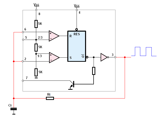
This circuit with the NE555 timer will work as a astable oscillator.

The simplified schematic will look like this:

enter image description here

When the pin3 (\$Q\$) is at HIGH state (very close to V supply for a CMOS version) The capacitor will be charging

And this charting current will flow from:

pin3--->Rt--->CT--->gnd--->V supply--->Into pin 8.

And this charging phase will last until the voltage across the capacitor do not reach the threshold voltage (VH = 2/3 Vcc).

$$T_H = R_t C_t \ln \left(\frac{V_{CC} - V_L}{V_{CC} - V_H}\right) $$

Then OUT (pin 3) is turned LOW (very closer to 0V but not equal) and the capacitor will start the discharge phase:

Ct positive plate--->Rt--->into pin 3--->and via gnd back to Ct negative plate.

And this phase will end when the capacitor voltage drops below the triggering voltage (VL = 1/3 Vcc) and then the OUT pin will switch again to HIGH again.

$$T_L = R_t C_t \ln \left(\frac{V_H}{V_L}\right) $$

And the cycle repeat.

And the period is

$$F = \frac{1}{T_H+T_L}=\frac{1}{R_t C_t \ln \left( \frac{V_H *(V_{CC} - V_L)}{V_L*(V_{CC} - V_H)}\right)}= \frac{1}{R_t C_t \ln(4)} = \frac{1}{1.386R_t C_t} $$

As for the output, the \$LC\$ circuit forms the second order low pass filter. Hence, if low pass filter cut-off frequency is equal or lower then the 555 timer frequency. At the output of the filler we will see the fundamental harmonics only (a sine-wave). What exactly are harmonics and how do they "appear"?

\$\endgroup\$

Your Answer

By clicking “Post Your Answer”, you agree to our terms of service and acknowledge you have read our privacy policy.

Not the answer you're looking for? Browse other questions tagged or ask your own question.