1
\$\begingroup\$

I would like to find out the internal resistance Ron of this IGBT device : http://www.infineon.com/dgdl/Infineon-IHW50N65R5-DS-v02_04-EN.pdf?fileId=5546d461464245d30146ae23713f0115

The Ron resistance is not included in the datasheet.

Is there a way to export Ron from the charts that are included ?

Thanks in advance

\$\endgroup\$

1 Answer 1

5
\$\begingroup\$

It's not a MOSFET, it is an IGBT, so doesn't have an Ron resistance in the way a MOSFET does.

An IGBT functions like a combined device with a low power MOSFET driving a bipolar transistor. Because the operating current density for bipolar transistors is higher than FETs an IGBT can carry higher currents than the same size FET.
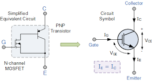
Simplified equivalent circuit of IGBT

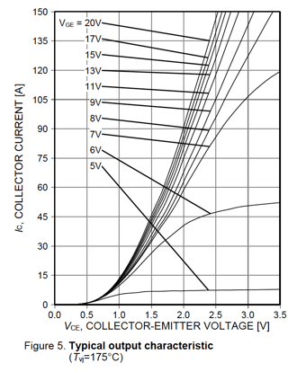
The data sheet gives the voltage drop at specific currents and has a curve in figure 5 on page 8 that could be used to determine the voltage drop at various currents. Notice that it does not intersect at zero as a MOSFET would and requires about 0.5v to start conducting. enter image description here
The Simulink model treats the IGBT DC output characteristic as having two segments:

  1. Vf - The voltage at which conduction starts

  2. Ron - The slope of the conduction after that point
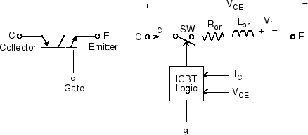
Simulink IGBT model

From the curve the Vf is 0.5V.

To calculate Ron draw a straight line through the curve from 0.5v to 2.5v. The current increases by ~140Amps over this 2V range. This is equivalent to a resistance of 2/140 = ~14mOhm (0.014 Ohms).

\$\endgroup\$
7
  • \$\begingroup\$ So @KevinWhite , in case that I want to do a simulation in Matlab/ Simulink if I use IGBT, I need to know the parameter, Ron. According to Simulink, Ron is the internal resistance Ron of the IGBT device, in ohms (Ω). The default value is 1e-3 Is it right to go in figure 5, select the Voltage drop according to the current of my application, and then find the Ron= V / I ? \$\endgroup\$
    – Yiannis S.
    Commented Jun 21, 2017 at 8:24
  • \$\begingroup\$ Are you using an IGBT model in simulink? Using the resistance value calculated as you describe will not be very accurate but may be adequate. It depends upon what you are looking for in the simulation. \$\endgroup\$ Commented Jun 21, 2017 at 14:22
  • \$\begingroup\$ yes I use the IGBT/diode from the library. In case that you can suggest another way to find out the R of my IGBT let me know. Thank you for your time. \$\endgroup\$
    – Yiannis S.
    Commented Jun 21, 2017 at 16:07
  • 1
    \$\begingroup\$ I looked at the IGBT model description and they have both a turn-on voltage (it would be about 0.5V for the device you selected) plus the Ron that would be the slope of the curve after it is turned on - this is not the same as what you calculated. If we draw a straight line from 0.5v to 2.5v the current increases by ~140Amps. This is equivalent to about 7 mOhm. \$\endgroup\$ Commented Jun 21, 2017 at 16:39
  • \$\begingroup\$ 0.5 V + 7 mohm seems resonable for a beefy IGBT. \$\endgroup\$
    – winny
    Commented Jun 21, 2017 at 16:56

Your Answer

By clicking “Post Your Answer”, you agree to our terms of service and acknowledge you have read our privacy policy.

Not the answer you're looking for? Browse other questions tagged or ask your own question.