9
\$\begingroup\$

enter image description here

This is a screenshot of IRF9640 MOSFET datasheet. Will you please tell me, what is meant by max and min value of Vgs threshold voltage. Also what they mean by test condition.

Whether the max and min values are only applicable for specified test condition? What will be the threshold voltage for a switching circuit and how the range varies?

My doubt is, for p channel mosfet to turn on Vgs < Vgs(th). For IRF9640 in what volt it will turn on -3 or -5? When i used in my application Vs is 6v and Vg is 3v hence Vgs=-3v but it won't turned on, Why? It turned on when Vgs=-3.3v.

If we consider -2v as threshold, it should turn on when Vgs=-3v. Why they given a range for threshold voltage. Whether we have to test each mosfet to know their threshold. What i am pointing is that, if we have two IRF9640, will Vgs(th) is differ from each other?

\$\endgroup\$
3
  • 5
    \$\begingroup\$ You mean Vgs(th) max, not Vgs(max)! The latter could easily be interpreted as the maximum allowed voltage across gate and source, a value typically between 10 and 20 volts. A different parameter entirely. Don't make up notation if you don't know what it means ;) \$\endgroup\$
    – marcelm
    Commented Jun 21, 2017 at 7:46
  • \$\begingroup\$ yeah i mean Vgs(th). I described it above \$\endgroup\$
    – vishnu m c
    Commented Jun 21, 2017 at 8:20
  • \$\begingroup\$ The span of Vgs is the manufacturing tolerance of the threshold voltage, i.e. the supplier will happily sell you parts with a Vgs,th of -4V. \$\endgroup\$
    – sstobbe
    Commented Jun 23, 2017 at 0:54

3 Answers 3

9
\$\begingroup\$

what they mean by test condition.

It refers to the conditions under which the parameter was tested. In this case the most important condition is ID = -250uA. This current has been chosen as the point where the FET is right on the threshold between being off and on (compare to On-State Resistance where the condition chosen is ID = 6.6A).

This is not the normal Gate drive voltage that would be applied. To fully turn on it needs approximately -10V.

what is meant by max and min value of Vgs threshold voltage

It means that the threshold voltage could be anywhere between -2.0V and -4.0V.

Gate threshold voltage is notoriously difficult to manufacture precisely because it is critically dependent on oxide thickness. The range of -2V to -4V refers to possible variation between individual units. So if you had 3 IRF9640's then one might be -2V, another -3V, and another -4V. Or they might all be -3V (you won't know until you test them).

This variation in threshold voltage also affects the turn-on voltage. So while the FET might 'typically' turn on reasonably well with -5.0V, it's not guaranteed. Therefore to ensure that all units will turn on fully you should drive the Gate with more voltage than the datasheet's 'Typical Output Characteristics" might suggest is necessary. For this FET the recommended Gate drive voltage is -10V.

\$\endgroup\$
7
\$\begingroup\$

This means that the threshold voltage between the Gate and Source is between -2V and -4V, meaning the Gate must be between 2-4V lower than the Source in order for it to be in it's 'on' state.

The third column on your screenshot is the test conditions, as it says in the datasheet. If you are doing a switching circuit, just make it a nice 5V circuit, that way you are more than covered, stick a pull-down or pull-up resistor on the gate and switch the 5V to turn it on and off.

Being above the maximum, you can be sure that this way, the MOSFET will be turning fully on and off each time it is switched.

\$\endgroup\$
6
  • \$\begingroup\$ Do you know why all MOSFET datasheets define a specific Id current when measuring the Vgs(th)? I have never learned that the threshold voltage depends on the current flowing through the channel. Or is it just to have some defined conditions for the measurements? \$\endgroup\$
    – nickagian
    Commented Jun 21, 2017 at 8:35
  • \$\begingroup\$ I think it is so they have a defined test condition. But the face they have a max and a min should take into account the current flowing through I would have thought. Can't say for certain though as I don't actually know! \$\endgroup\$
    – MCG
    Commented Jun 21, 2017 at 8:40
  • \$\begingroup\$ Thank you for your answer MCG. But my doubt is, for p channel mosfet to turn on Vgs < Vgs(th). For the above one in which volt it will turn on -3 or -5? When i used in my application Vs is 6v and Vg is 3v hence Vgs=-3v but it won't turned on, Why? It turned on when Vgs=-3.3v \$\endgroup\$
    – vishnu m c
    Commented Jun 22, 2017 at 22:24
  • \$\begingroup\$ If we consider -2v as threshold, it should turn on when Vgs=-3v. Why they given a range for threshold voltage. Whether we have to test each mosfet to know their threshold. What i am pointing is that, if we have two IRF9640, will Vgs(th) is differ from each other? \$\endgroup\$
    – vishnu m c
    Commented Jun 22, 2017 at 22:34
  • 1
    \$\begingroup\$ They will never be exactly the same, so chances are there will an slight variations in their Vgs(th) ranges. That is why they have a max and min rating, just to make sure it's covered. I have found that if you stick with the max, you won't go wrong! \$\endgroup\$
    – MCG
    Commented Jun 22, 2017 at 22:45
6
\$\begingroup\$

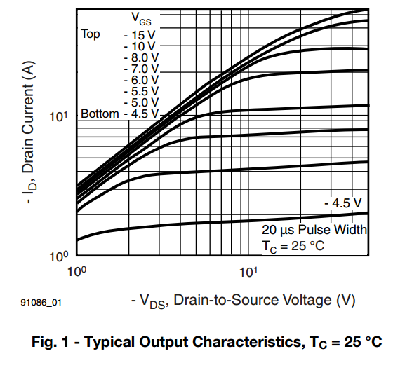
This is a P channel mosfet and somewhere between -2 volts and -4 volts applied to the gate relative to the (more positive) source, the current taken from source to drain will be 250 uA. Drain is connected to gate in this test. It is somewhat indicative of where the device starts to turn on. However, a better picture of the turn-on characteristics is shown in this picture: -

enter image description here

\$\endgroup\$
5
  • \$\begingroup\$ Pls review my comment in MCG's answer \$\endgroup\$
    – vishnu m c
    Commented Jun 22, 2017 at 22:27
  • \$\begingroup\$ There is a range because there is inexactitudes involved. Mosfet cannot be relied upon until the max Vgs(th) is significantly exceeded hence the diagram in my answer. \$\endgroup\$
    – Andy aka
    Commented Jun 22, 2017 at 22:37
  • \$\begingroup\$ Sorry, i didn't get you. Will you pls explain \$\endgroup\$
    – vishnu m c
    Commented Jun 22, 2017 at 22:39
  • \$\begingroup\$ Maxinmum threshold voltage is -4v for the above one, is that right? So for reliable switching it should be less than -4v ? \$\endgroup\$
    – vishnu m c
    Commented Jun 22, 2017 at 22:40
  • 2
    \$\begingroup\$ Look at the graph. The minimum curve is when the gate is 4.5 volts below the source. If you wanted to control a load of 2 amps, the volt drop across source to drain will be typically 40 volts i.e. not very good. However, the next highest curve is with the gate 5 volts lower than the source and this is a totally different picture because a load of 2 amps results in a drain source drop of only 1 volt. Think about what the graph is telling you. \$\endgroup\$
    – Andy aka
    Commented Jun 22, 2017 at 23:27

Your Answer

By clicking “Post Your Answer”, you agree to our terms of service and acknowledge you have read our privacy policy.

Not the answer you're looking for? Browse other questions tagged or ask your own question.