0
\$\begingroup\$

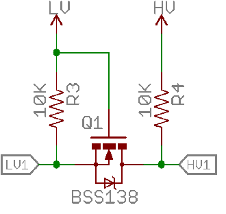
I have an Intel Edison communicating with a Olimexino-85S by i2c. The Intel Edison works with 1.8V levels while Olimexino does it whit 5V levels. I am using a Level Converter with pull-up resistors in order to communicate them. The scheme of one channel of the level converter is as follows:

enter image description here

  • LV: 1.8 V
  • HV: 3.3 V
  • LV1: I2C line connected to Intel Edison
  • HV1: I2C line connected to Olimexino-85S

I have powered the HV part of the Level Converter with 3.3V although the Olimexino works with 5V levels. But everything works good. How is it possible?

Thanks in advance,

CarolusM.

\$\endgroup\$
1
  • \$\begingroup\$ Please ask a specific quesiton, its unclear what your actually asking, a good question will generate good answers \$\endgroup\$
    – Voltage Spike
    Commented Jun 29, 2017 at 6:04

2 Answers 2

1
\$\begingroup\$

According to Olimexino-85S product description it doesn't states it works with 5V only. Instead it only says it runs ATtiny85-SU MCU. And the schematics doesn't seems to have any sort of voltage regulator. Looking the the ATtiny85-SU datasheet it states that ATtiny85 can work withing 2.7 - 5.5V range. So 3.3 V are perfectly fine for running this MCU.

\$\endgroup\$
4
  • \$\begingroup\$ I fail to follow the logic here. The fact that ATtiny85 can be powered with 2.7 - 5.5V doesn't mean any voltage in between is OK on its data pins. \$\endgroup\$ Commented Jun 26, 2017 at 12:46
  • \$\begingroup\$ @DmitryGrigoryev refer to the section 21.2 "DC Characteristics" of the datasheet. HIGH and LOW levels of the digital I/O pins are "tied" to Vcc. Where LOW level are -0.5 V to 0.3 * Vcc, and HIGH are 0.6 * Vcc - Vcc + 0.5 V. \$\endgroup\$
    – NStorm
    Commented Jun 26, 2017 at 13:08
  • \$\begingroup\$ Nevermind me. I still don't see how Vcc is related to 3.3V. Perhaps a proper circuit diagram posted by the OP would have helped, but oh well. \$\endgroup\$ Commented Jun 26, 2017 at 13:22
  • \$\begingroup\$ @DmitryGrigoryev well yes it's hard to tell without knowing the circuit. I've assumed that ts connected that Olimexino board to 3.3 V supply. But even if MCU Vcc are 5 V, it's HIGH level minimum voltage would be 0.6*5 = 3.0 V, so a 3.3 V level on IO port will still be enough. \$\endgroup\$
    – NStorm
    Commented Jun 26, 2017 at 13:47
0
\$\begingroup\$

From the website for the Olimexino-85S: https://www.olimex.com/Products/Duino/AVR/OLIMEXINO-85S/open-source-hardware

The image for the pin out diagram says that VCC is 3.6v when powered by USB.

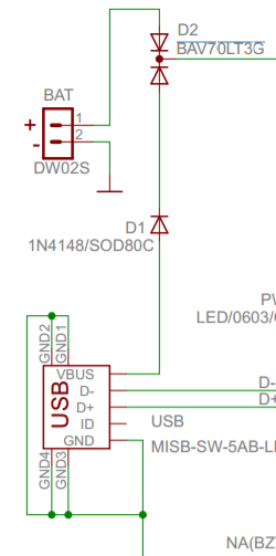
From the schematic (shown below) the VBus line from the USB connector goes through two diodes, D1 and D2. From their datasheets they both have a maximum forward voltage drop of 1V and 1.25V respectively but this is dependant on the current draw. So the combination of these two voltage drops at whatever current the chip is drawing will account for the drop from the USB's 5V rail to the 3.6V at VCC. A 3.3V logic signal will comfortably trigger a 3.6V device.

enter image description here

\$\endgroup\$

Your Answer

By clicking “Post Your Answer”, you agree to our terms of service and acknowledge you have read our privacy policy.

Not the answer you're looking for? Browse other questions tagged or ask your own question.