I am not understanding something very fundamental here , I have read that an RC circuit can be used as a clock source. From this I assume a DC input. Playing around with my oscilloscope the only time I see an RC circuit oscillate is with an already oscillating input, throwing in a DC input there is no oscillating just the obvious blocking of DC by the cap, so how does an RC circuit work as on oscillator with a DC input? And I know you can make fancy ones with more components but I mean a very simple resistive/capacitive circuit? Thanks in advance.
-
1\$\begingroup\$ You might want to go here, electronics-tutorials.ws/oscillator/rc_oscillator.html , to read a modest discussion of using RC for oscillation. Also, we recently had a question about a circuit that supports a damped oscillation based on that idea: electronics.stackexchange.com/questions/313172/… \$\endgroup\$– jonkCommented Jun 28, 2017 at 5:09
3 Answers
You have basically already answered your own question. A simple R & C circuit configured as a low pass or a high pass filter circuit is not capable of sustaining oscillation. For oscillation you need something that provides feedback from output to input of the circuit with 180 degree phase shift. Almost always that requires the circuit to contain some type of active component that adds gain so that the oscillation can be sustained. Without it any oscillation from a Time 0 application of the feedback will die out in a few cycles due to the lossy nature of the circuit.
If you do get an R & C circuit to oscillate with some active components (transistor, MSFET, opamp, comparator, tube, valve) you can then use the resulting AC waveform as a clock signal should its amplitude, frequency and average voltage level meet the needs of the clock consumer. Voltage and amplitude characteristics are easily adjusted with some additional circuitry. Frequency can be changed by either changing R & C values in the oscillator circuit or using counters and flip flops to divide the frequency to a lower value.
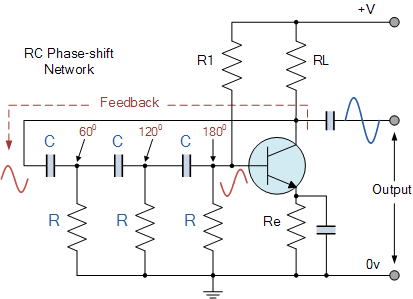
You're correct about oscillators being used at clock. A lot of computing systems use RC oscillators to have a clock reading for a particular processor. But you need more than just a filter to have an oscillator... look at the picture below (I got this from Electronic Tutorials).
As you can see, in order to have an oscillator, you need a feedback network. Depending on how many branches you have with these capacitors and resistors, it can change the difference in phase shifting.
The output frequency can be defined as \$ f_r = \frac{1}{2\pi RC\sqrt{2N}} \$, where \$ N \$ is the number of RC branches that you have.
This is one out of many solutions you can have for an RC Oscillator. You may use an Op Amp if you desire for an another example.
Another Astable uses a CMOS Schmitt Inverter with a large R and small C.
This Astable Osc uses negative feedback for centre DC input bias and Hysteresis to determine transition time ramp (triangle wave) with a square wave out. f=0.72/RC for input hysteresis= Vdd/3 .

simulate this circuit – Schematic created using CircuitLab

