0
\$\begingroup\$

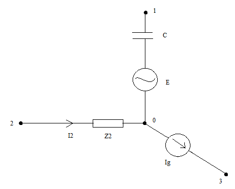
For the part of the circuit of sinusoidal circuit given below, the following data is given (effective values): $$E=10V,I_g=2\sqrt 3 A,I_2=2A.$$

Impedance of conductor is $$Z_C=5\Omega.$$

Current Ig is leading in phase with regards to E for 2pi/3, and E is running late in phase with regards to I2 for pi/2.

Evaluate effective value of voltage U10.

enter image description here

I think that the following intuitive solution is completely incorrect:

By using potential of nodes method on branch 1-0, if we set 0 node as referent, we have: $$\underline{V_1}\frac{1}{\underline{Z_C}}=\frac{\underline{E}}{\underline{Z_C}}\Rightarrow \underline{V_1}=\underline{E}$$

Could someone explain why this solution is incorrect?

What is a correct approach?

\$\endgroup\$
6
  • \$\begingroup\$ "Evaluate effective value of voltage" - what voltage? \$\endgroup\$
    – Andy aka
    Jun 29, 2017 at 15:41
  • \$\begingroup\$ @Andy aka, Voltage U10. I said that in the new line from the last question. \$\endgroup\$
    – user156262
    Jun 29, 2017 at 15:42
  • \$\begingroup\$ Eh??????????????? \$\endgroup\$
    – Andy aka
    Jun 29, 2017 at 15:56
  • \$\begingroup\$ @Andy aka, Just read the last sentence of the problem and include U10. \$\endgroup\$
    – user156262
    Jun 29, 2017 at 15:59
  • \$\begingroup\$ Just fix the question dude!! \$\endgroup\$
    – Andy aka
    Jun 29, 2017 at 16:05

2 Answers 2

1
\$\begingroup\$

First apply Kirchhoff's current rule at junction 0. That gives you the current in the 1-0 branch, because you already know the other two currents. Now just trace a path from 0 to 1 algebraically adding voltages. Then you have the answer. That's basically what the first person said.

I think the mistake you're making is that you're assuming zero current in the 1-0 branch. You cannot arbitrarily do so. The branch is not open, it's just that any other connection, it might have, isn't shown.

\$\endgroup\$
0
\$\begingroup\$

I hope this helps: Capacitors transmit displacement current, they do not allow actual flow of electrons.

So the initial equality: $$\frac{V_1}{Z_c} = \frac{E}{Z_c}$$ is invalid.

The voltage between 1 and 0 will be E+ the voltage across the capacitor. If the capacitor voltage is opposite in polarity to E, then the magnitude of V_1 could be less than the magnitude of E.

The trick is to find the displacement current though the capacitor, the following should help.

$$I_g=I_2 +\frac{V_1-E}{Z_c}$$

Back To Phase Shifting

For the voltage source E, it is treated as a short circuit for current flow.

   Ig is leading E by 120 degrees.

   I2 is leading E by 90 degees.

Converting from polar to rectangular coordinates: $$i_g = 3+j1.732$$ $$i_2 = 0+j2$$

$$i_c = i_g-i_2$$ I got $$3-j0.268=3.0\angle-5.1^o$$

So v across c: $$V_c = I_c \times Z_c$$ I got $$15\angle-5.1^o$$

So V1: $$V_1= V_c+E$$ I got $$24.98\angle-3.1^o$$

\$\endgroup\$
5
  • \$\begingroup\$ @A Gern, Do you mean that the solution from my original post, $$\underline{V_1}=\underline{E}$$ is correct? \$\endgroup\$
    – user156262
    Jun 29, 2017 at 16:23
  • \$\begingroup\$ @A Gern, Could you clarify? Please give detailed solution if possible. \$\endgroup\$
    – user156262
    Jun 29, 2017 at 16:26
  • \$\begingroup\$ @A Gern, How to determine the voltage across the capacitor? \$\endgroup\$
    – user156262
    Jun 29, 2017 at 16:59
  • \$\begingroup\$ Updated my first answer, using the algebra you can ignore the difference between displacement and 'real' current, that just describes the physics of the current flow. \$\endgroup\$
    – A Gern
    Jun 29, 2017 at 17:06
  • \$\begingroup\$ @A Gern, I am really stuck at this problem. Could you give a detailed solution? \$\endgroup\$
    – user156262
    Jun 29, 2017 at 17:17

Your Answer

By clicking “Post Your Answer”, you agree to our terms of service and acknowledge you have read our privacy policy.

Not the answer you're looking for? Browse other questions tagged or ask your own question.